36
TimeProvider 500 2.0 User’s Guide
098-00172-000 Revision A – December, 2009
Chapter 2 Installation & Configuration
Installation
Rack Mounting the TimeProvider 500
The installation procedure described in this section provides general guidelines for
installing the TimeProvider 500. Refer to
TimeProvider 500 System and Accessory
, on page 99 for information about available rack mount kits and
mounting adapter bracket kits.
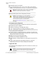
When installing the TimeProvider 500, always follow applicable local electrical
standards. Use the following steps to mount the TimeProvider 500 in a rack.
1. Attach the rack mounting brackets to the TimeProvider 500 using 6-32 x 1/4-inch
screws.
2. Ensure that the mounting brackets on both sides are attached at equal distances
from the front of the unit.
3. Mount the TimeProvider 500 to the front of the equipment rack rails with four
screws and associated hardware as shown in
.
Rack Mounting Safety Instructions
Elevated Operating Ambient
Temperature
- If installed in a closed or multi-unit
rack assembly, the operating ambient temperature of the rack environment may
be greater than room ambient temperature. Therefore, consideration should be
given to installing the equipment in an environment compatible with the maximum
ambient temperature of the TimeProvider 500, which is
+65
C
.
Reduced Air Flow
- Installation of the equipment in a rack should not compromise
the amount of air flow required for safe operation of the equipment.
Mechanical Loading
- Do not mount the equipment in the rack in a manner that
creates a hazardous condition due to uneven mechanical loading.
Circuit Overloading
- When connecting equipment to the supply circuit, consider
the effect that overloading of the circuits might have on overcurrent protection
and supply wiring. Refer to the equipment nameplate ratings when addressing
this issue.
Reliable Earthing
- Reliable earthing of rack-mounted equipment should be
maintained. Pay particular attention to supply connections other than direct
connections to the branch circuit (for example, use of power strips).
shows a TimeProvider 5000 grandmaster clock at the top, dual-mounted
TimeProvider 500s in the middle, and a single-mounted TimeProvider 500 at the
bottom.
Note
: Using screws other than 6-32 x 1/4 inch could cause damage
to the unit. Always use the proper screws for the equipment rack.
Содержание TimeProvider 500
Страница 10: ...Table of Contents 10 TimeProvider 500 2 0 User s Guide 098 00172 000 Revision A December 2009 ...
Страница 12: ...List of Figures 12 TimeProvider 500 2 0 User s Guide 098 00172 000 Revision A December 2009 ...
Страница 122: ...122 TimeProvider 500 2 0 User s Guide 098 00172 000 Revision A December 2009 Chapter 4 CLI Commands Show Commands ...
Страница 146: ...146 TimeProvider 500 2 0 User s Guide 098 00172 000 Revision A December 2009 T1 Format ...
Страница 174: ...Index W W 174 TimeProvider 500 2 0 User s Guide 098 00172 000 Revision A December 2009 ...


