background image


50 

     SVANTEK 977W User Manual 
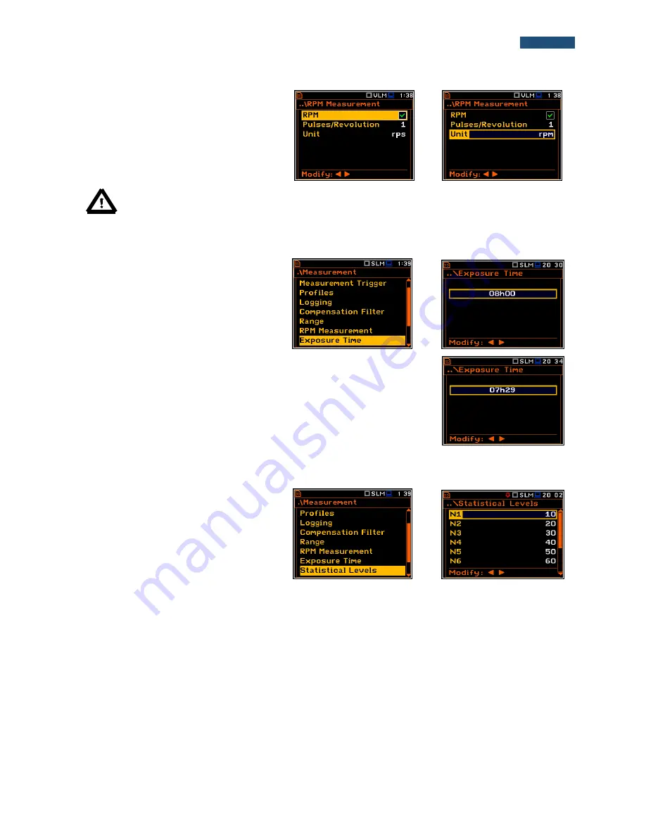
The 

Pulse/Rot.

 position enables the user to 

select the number of pulses per one rotation. 
Available values are in the range: 

1

..

360

.  

The 

Unit

 position enables the user to select 

the unit of the measurement. Two option are 
available: revolutions per minute (

rpm

) and 

revolutions per second 

(rps

). 


Note: 


The RPM results are always registered in the logger file as a logger results (with the logger 

step) and as a summary results (with the integration period step). 

5.9 

Setting the exposure time - Exposure Time  

The 

Exposure Time

 enables the user to set 

the  desired value  of  the  workday  exposure 
time that is used for the calculation of 

LEPd


(cf.  App. D  for  the  definitions  of  the 
functions).  This  sub-list  is  available  only  in 
the sound mode. 


<ENT> 


The 

Exposure Time

 values are within the range [00h01, 08h00]. The required 

value can be set using the 

◄ or ► push-buttons – after each button press the 

exposure time is decremented / incremented by one minute. The step can be 
decremented / incremented in 30 minute steps by pressing the 

◄ or ► push-

buttons together with 

<Shift>

.  


5.10 

Setting ten statistical levels - Statistical Levels


The 

Statistical Levels

 position is available 

only in case of the 

Sound Meter 

modes.  

In  the 

Statistical Levels

  window,  it  is 

possible  to  define  ten  statistical  levels, 
named  from 

N1

  to 

N10

,  to  be  calculated, 

displayed  and  saved  in  the  files  together 
with the main results.  


<ENT> 


The  default  statistical levels  have  the following  settings: 

10

20

30

40

50

60

70

80

90

  and 

95

. All values 

should be within the integer range [1, 99]. Each individual value can be set independently from the others. The 
selection of the 

Nx

 in the list is made by means of the 

▲ or ▼ push-buttons.  

The upper 

Nx

 is visible on the display and becomes active for editing after pressing the 

 push-button together 

with 

<Shift>

. The lower 

Nx

 is visible on the display and becomes active for editing after pressing the 

 push-

button together with 

<Shift>

.  

The 

Nx

 current value is decreased / increased in 1 % steps by means of the 

◄ or ► push-buttons. The step can 

be decreased / increased up to ten % by simultaneously pressing the 

◄ or ► push-buttons with 

<Shift>

.  

The sub-list is closed and the instrument returns to the 

Measurement

 list after pressing the 

<ENTER>

 (with the 

confirmation of all changes made in this list) or 

<ESC> 

push-button (ignoring all changes). 


Содержание SVAN 977W

Страница 1: ...USER MANUAL SVAN 977W SOUND VIBRATION ANALYSER Warsaw February 2017 Copyright 2017 SVANTEK All rights reserved...

Страница 2: ...demarks Trademarks or registered marks in this manual belong to their respective manufacturers Microsoft and Windows are registered trademarks of Microsoft Corporation The Bluetooth word mark and logo...

Страница 3: ...rument s calibration Calibration 26 4 3 1 System Check 27 4 3 2 Calibration by Sensitivity in case of Acoustic signal 27 4 3 3 Calibration by Sensitivity in case of Vibration signal 28 4 3 4 Calibrati...

Страница 4: ...MANAGING THE FILES File 62 7 1 Managing files saved in the external memory File Manager 63 7 1 1 Assigning the directory for saved files Set as Working Dir 63 7 1 2 Opening file Open 64 7 1 3 Deletin...

Страница 5: ...Selecting event records by ID Find Records by ID 85 10 2 4 Selecting event records by date Find Records by Date 86 10 3 Data Logger dumping Data Dump 86 10 4 Firmware memory dumping Program Dump 86 10...

Страница 6: ...w 104 12 2 6 Selection of the spectrum type in Vibration mode Spectrum Type 104 13 REVERBERATION TIME MEASUREMENT RT60 105 13 1 Selection of RT 60 function 105 13 2 Setting the RT60 analysis 105 13 3...

Страница 7: ...s the WELMEC requirements for built for purpose measuring instrument type P for acoustic measurements Time domain waveform signal recording on the external SD card is available as an option and advanc...

Страница 8: ...ucer is equal to 0 5 Hz 14 kHz Parallel RMS MTVV or Max Peak Peak Peak measurements HP HP1 HP3 HP10 Vel1 Vel3 Vel10 VelMF Dil1 Dil3 Dil10 and Wh weighting filters 1 1 Octave and 1 3 Octave real time a...

Страница 9: ...ometer SA 15 power supply SA 31 external charger for four AA rechargeable batteries 1 6 Software options available SV 977_2 1 3 octave analysis for the SVAN 977W SV 977_4 FFT analysis option for the S...

Страница 10: ...like with a computer keyboard e g while typing the filename both Shift and the second push button must be pressed together two finger operation as 2nd Fun this push button can be pressed and released...

Страница 11: ...Calibration sub list S P This push button ESC pressed together with Alt enables the user to pause or break the measurement process temporarily during the measurement or to save the setup file if the...

Страница 12: ...ave to be activated path Menu Measurement Logging Logger Results To enter the marker mode the user must press Shift and Alt push buttons simultaneously during the measurement Then four available marke...

Страница 13: ...eed it is widely used in all PCs In the instrument the standard 4 pin socket is used The Serial socket is Serial Port provides data transfer using RS232 data format but in TTL logic standard by means...

Страница 14: ...s of six lists which also contain sub lists or positions elements The main list is opened after pressing the Menu push button This list contains the following sub lists Function Measurement Display Fi...

Страница 15: ...me column by means of or with Shift all values in the same line by means of or with Shift Complex parameters Some parameters like Start Hour Start Day etc are complex consisting of more than one value...

Страница 16: ...ging them In this case using the best NiMH type the operation time can be increased up to 16 h 4 8 V 2 6 Ah External DC power source 7 V DC 16 V DC 1 5 W SA 17A external battery pack operation time 24...

Страница 17: ...s power can be achieved by reducing the brightness of the screen when possible The settings of Brightness and power saver function may be done in the Screen Setup window path Menu Display Screen Setu...

Страница 18: ...th 1 second step Logger On Logger Step 1 s Logger Results Peak Max Min and Leq for all profiles and summary results saving including Statistics Other functions are switched off like measurement trigge...

Страница 19: ...te icon is displayed when the wave recording is active wave files with extension WAV are saved automatically Trigger Level icon is displayed when the Level trigger is waiting for fulfilment condition...

Страница 20: ...when the wireless transmission GPRS modem is active but there is no connection with Host or SvanNET or icon is displayed if there is no GPRS connection or icon is displayed if there is connection with...

Страница 21: ...e logger file name is defined automatically using a pattern LLdd where LL is the string of letters so called prefix and dd is a string of digits that forms a number path Menu Measurement Logging Logge...

Страница 22: ...ses Save Alt ENTER after the measurement the instrument opens the Logger Setup window path Menu Measurement Logging Logger Setup with the selected Logger Name position and the file name with the incre...

Страница 23: ...easurement Logging Logger Setup the manual saving of Summary Results is possible only through File Manager If the user press Save push button after the measurement the instrument opens the Logger Setu...

Страница 24: ...or by creating the New File in the Setup Manager list S P There is no automatic option for the setup files saving but the instrument always generates new setup name automatically with default prefix...

Страница 25: ...Meter SLM function provides the user with functions meeting the standard IEC 61672 2013 for Type 1 accuracy and the Vibration Level Meter VLM meeting the standard ISO 8041 2005 The instrument can als...

Страница 26: ...Calibr by Measurement in the Sound Meter mode the user should have a special right and know the Code to unlock these positions ENT Note The new calibration factor for Sound Meter mode can be saved if...

Страница 27: ...the ESC and Pause push buttons do not operate but it is possible to stop the measurement using the Start Stop push button Waiting for the calibration measurement to begin a Delay is counted down Measu...

Страница 28: ...35 0 V Pa calibration factor is equal to 60 0 dB If the new calibration factor differs more than 1 1 dB from the factory one or the last changed by the authorised service the instrument will not save...

Страница 29: ...signal ca 124 dB or different type of acoustic calibrator dedicated for microphones In any case before starting the calibration measurement the user has to set the level of the signal generated by th...

Страница 30: ...tion mode is 10 m s2 at 159 2 Hz Remember to change this level if using an alternative vibration calibration signal source 3 Attach the instrument s accelerometer to the vibration calibrator using an...

Страница 31: ...ibration History window has different content because no WELMEC requirements is applied to the Vibration Meter mode ENT 4 3 7 Clear calibration records Clear Calibr History The user can clear all stor...

Страница 32: ...Calibration enables the user to perform additional calibration after a measurement session and add the results to the file saved in the memory The Post Calibration list includes three options for sav...

Страница 33: ...to switch on required microphone compensation filter Range enables the user to set the correct measurement range RPM Measurement enables the user to set the RPM measurements parameters Exposure Time...

Страница 34: ...tton to the start of the measurements to allow synchronisation with the instrument s RTC The Start Sync parameter can be set as Off 1m 15m 30m and 1h For example if 1h was selected then each measureme...

Страница 35: ...f the Leq LEPd LN and Sel functions do not depend on the detector time constant Fast Slow or Impulse the results are displayed without the indicator of the detectors selected in the profiles In this c...

Страница 36: ...ement Trigger can be switched off using the push buttons ENT Triggering is switched on if one of its six available modes is selected Slope Slope Level Level Grad or External If the instrument works wi...

Страница 37: ...assumed that only one measured result can be used as a source of the triggering signal in the Level Meter mode namely the output signal from the RMS detector coming from the first profile which is den...

Страница 38: ...or RMS Ovl Peak P P MTVV in case of Vibration measurements are measured and saved in the file with the step defined by Integration Period parameter as many times as defined by the Repetition Cycles p...

Страница 39: ...sts of seven positions Logger Setup Logger Results Summary Results Logger Trigger Event Recording Marker Setup and Wave Recording ENT 5 4 1 Setting the logger general parameters Logger Setup The Logge...

Страница 40: ...to 59 minute and up to 1 hour The Logger Name position enables the user to define the logger file name The default name is L The name can be up to eight characters long After pressing the or push butt...

Страница 41: ...c measurements and Peak P P Max and RMS for vibration measurements and results taken from the meteo module Meteo which will be recorded to the logger file during the measurement period with the logger...

Страница 42: ...d taken from the Logger Step path Menu Measurement Logging Logger Setup all measurement results up to the moment the triggering signal falls below the Level the results recorded directly after the ful...

Страница 43: ...etup The result of the calculation is presented in the same line at the right side of the display 5 4 5 Setting the event recording Event Recording The Event Recording position enables the user to act...

Страница 44: ...gger icon appears alternatively with the note icon If the Integr Period trigger was defined the signal is recorded every time the measurement starts and ended after the Integration Period time defined...

Страница 45: ...ts per sample 2s for 48 kHz 4s for 24 kHz and 8s for 12 kHz for 16 bits per sample 4s for 48 kHz 8s for 24 kHz and 16s for 12 kHz 5 4 6 Setting the markers Marker Setup Marker is used to mark or highl...

Страница 46: ...recording 12 kHz 24 kHz and 48 kHz The Bits Per Sample position enables the user to select the number of recorded bits per sample 16 or 24 The Filter position enables the user to select the weighting...

Страница 47: ...e recording Level can be set with 1 dB steps in the range from 24 dB to 136 dB in sound modes and from 1mm s2 60 dB to 10 km s2 200 dB in vibration modes In case of Vibration measurements the level ca...

Страница 48: ...will be ignored The Free Field and Diffuse Field filters enable the user to set compensation for sound measurements in the free field conditions or in the diffuse field conditions The microphone suppl...

Страница 49: ...e The calibration factor is always added to the range limits For example if calibration factor is equal to 0 5 dB the range will be changed automatically lower and upper limits will be increased by 0...

Страница 50: ...ith Shift 5 10 Setting ten statistical levels Statistical Levels The Statistical Levels position is available only in case of the Sound Meter modes In the Statistical Levels window it is possible to d...

Страница 51: ...t to start The required hour and minute can be selected in a special window which is opened by means of the or push buttons To set hours or minutes the user should enter the left or right field by pre...

Страница 52: ...o do this the user should set the parameters of the Timer function the measurement parameters path Menu Measurement General Settings name the file path Menu Measurement Logger Logger Setup and finally...

Страница 53: ...trum analyser functions Spectrum Type enables the user to change the spectrum type presented on the display Acceleration Velocity and Displacement This position appears only in spectrum analyser funct...

Страница 54: ...resented there belongs to the range 1 Integration Period Note In case the RMS Integration is linear path Menu Measurement General Settings RMS Integration Lin for the Leq Sel Le LEPd and LN results Li...

Страница 55: ...Sound measurements or HP HP1 HP3 HP10 Vel1 Vel3 Vel10 VelMF Dil1 Dil3 Dil10 Wh in case of Vibration measurements 5 The value of the measured function 6 Units of the measured value 7 Elapsed time shows...

Страница 56: ...s or I Imp F Fast S Slow in case of Sound In case of Vibration measurements this field is skipped 7 Units of the measured value 8 The value of the measured function 9 Elapsed time shows the current se...

Страница 57: ...selected for logging the logger plot can be viewed Fields description of the Logger view 1 Y scale 2 Logger plot 3 Name of the logged result and profile number 4 Name of the file 5 Real Time Clock 6...

Страница 58: ...Slow or Imp 6 Averaging filter used A B C or Z 7 The sampling interval for the LN values calculated by the meter 0 1 s 8 Cursor position 9 Value of the selected statistical level LN and units dB The...

Страница 59: ...can be presented in Logarithmic dB or Linear for example m s2 units It depends on the Scale parameter value For example 10 m s2 can be presented as 140 dB The Resolution position defines the number of...

Страница 60: ...en Setup The Screen Setup window enables the user to set the brightness of the display and to switch on the screen saver ENT Brightness of the display The Brightness position enables the user to set t...

Страница 61: ...d from last use of any push button to the power saver mode This delay period can be set for Dim screen on idle from 5 s to 60 s and for Screen off on idle from 1 m to 60 m The ENTER push button must b...

Страница 62: ...hen an SD Card is inserted into the card slot under the bottom cover of the instrument If there is no SD card after user s attempt to enter any position in the File list the instrument will generate w...

Страница 63: ...le Manager list is New Directory which enables the user to create the new directory To do this the user should enter the directory in which the new one will be created and press the ENTER push button...

Страница 64: ...the file name To see next cycle data the user should select the record counter position by means of or push button and then change the record number by means of the or push button pressed together wi...

Страница 65: ...rated and rename command will not be performed After pressing any key the instrument will return to the editor window ENT 7 1 6 Viewing information about files Info The user can view information about...

Страница 66: ...Up to 8 characters can be used to name a setup ENT Loading the setup files To load settings saved in the setup directory the user should press ENTER on the selected file Then the user should confirm...

Страница 67: ...Stop push buttons Multifunction I O enables the user to select the available functionality of the I O port RTC enables the user to set the Real Time Clock Wireless Transfer enables the user to select...

Страница 68: ...smission Baud Rate speed can be selected from the following available values 1200 bits second 2400 bits s 4800 bits s 9600 bits s 19200 bits s 38000 bits s 57600 bits s or 115200 bits s The selection...

Страница 69: ...IEPE Current position enables the user to choose the correct IEPE current supply IEPE Off or IEPE Current 1 5 mA and IEPE Current 4 5 mA ENT 8 6 Programming the keyboard Keyboard Settings The Keyboar...

Страница 70: ...transmitted from the input of the instrument to its output without any digital processing i e frequency filtering the input of the digital signal used as an external trigger to start the measurements...

Страница 71: ...should be checked If the measured result level is greater than selected alarm level Alarm Level the instrument will generate alarm signal on the I O socket The measurement results from the first prof...

Страница 72: ...time in the limited range This range increases by six seconds each day from the date of the RTC correction by service For example after 7 days the user can adjust the clock by 42 seconds and after a y...

Страница 73: ...network type and set the parameters of the data transmission ENT 8 9 1 Selection of the network type Network It is possible to select one of two options Off and GPRS Depending on the settings in the N...

Страница 74: ...on the SIM card several options are possible some of them are recognized by the modem none no verification required PAP CHAP MsChap denotes MsChap in version 1 Send SMS selecting this option will conf...

Страница 75: ...or the port number This number denotes a port on which a communication socket will be configured for data exchange between remote host and the station Registration Port allows the user to enter up to...

Страница 76: ...onfigure the e mail service used for alarm notification For more information about alarm notification see Appendix J Alarm notification The E mail Settings window contains the following positions If S...

Страница 77: ...ommunicate with the mail server on the default port 25 for normal calls 465 with SSL Disabling of Default Port will initiate the Port position where the user will be able to set its own port Editing e...

Страница 78: ...s in which the results of the measurements are to be viewed This position appears only in Vibration modes Warnings enables the user to switch the warnings on or off that can be displayed during the no...

Страница 79: ...range from 1 nms 1 to 100 nms 1 In the Dil position the user can set the reference level of the displacement signal in the range from 1 pm to 100 pm Reference level for sound measurements In case of s...

Страница 80: ...rting the new measurement process If Save option is chosen then the measurement results are saved Checking free space on the external disk The Ext Disk Free Space position switches on or off the verif...

Страница 81: ...er to perform the dump of internal unit memory allocated to the firmware The memory dump is saved in two files on the SD card Status enables the user to view information about the registered in the We...

Страница 82: ...2 Selecting data records by ID Find Records by ID The Find Record By ID position opens the window where the user can select with the use of or and or push buttons the required record ID number ENT Af...

Страница 83: ...er to view all records All Records to filter records Filter Records to find the required record by its identificatory number Find Record By ID or to find required record by the date of its creation Fi...

Страница 84: ...om Daylight Saving Time DST to a Standard Time STD the second page consists of five positions which describe the type of change in this case Standard Time previous time of the instrument display Old p...

Страница 85: ...n the Appendix W 10 2 2 Filtering event records Filter Records The Filter Records position enables the user to choose the filter for event records selection by types of events ENT After choosing Date...

Страница 86: ...as a file on the SD card After pressing ENTER the display shows the directory tree and the user may select the directory where the file with the data records dump will be created ENT During data memor...

Страница 87: ...he status of the memory dedicated for the welmec records data and event records number recorded and available ENT 10 6 Modification of Welmec related parameters Service The Service sub list enables th...

Страница 88: ...ess ENTER The calibration factor is calculated after pressing the ENTER push button in relation to the nominal value of 35 0 mV Pa To avoid calculation the user should leave the Calibration sub list b...

Страница 89: ...measurement by pressing the Start Stop push button after stabilisation of the calibration measurement result The calibration delay time is set to 3 seconds Waiting for the start of the measurement the...

Страница 90: ...rial number ENT 10 6 4 Setting the microphone serial number Microphone The Microphone position enables the authorised user to input the microphone serial number ENT 10 6 5 Repair registration Register...

Страница 91: ...iles for Level Meter calculations The spectra are always linearly averaged Thus the Total values for 1 1 Octave or 1 3 Octave analysis can be different from those obtained for the profiles if the RMS...

Страница 92: ...ter path Menu Measurement Logging Logger Setup Logger Step For each octave or one third octave band the RMS result is calculated and presented as a bar on the spectrum plot Besides the RMS results for...

Страница 93: ...nts ENT Selection of the band The Band position defines the applied band of 1 1 Octave or 1 3 Octave analysis Available bands of the sound analysis are as follows 1 1 Octave o Audio 31 5 16k 10 filter...

Страница 94: ...ards C type 1 according to the IEC 651 and IEC 61672 1 standards B type 1 according to the IEC 651 standard Z type 1 according to the IEC 61672 1 standard For vibration analysis with Full band HP type...

Страница 95: ...ing the various parameters which are mainly dedicated for the control of the spectrum view The following positions are used for setting the presentation of the 1 Octave and 1 3 Octave results Display...

Страница 96: ...t spectrum line by simultaneously pressing the or buttons with Shift The band central frequency and the appropriate value are presented in the line below the plot 11 3 2 Setting scale of the spectrum...

Страница 97: ...ng the grid on off The Grid enables the user to switch on or off the horizontal grid lines in the spectrum view 11 3 3 Selection of the spectra to be viewed Spectrum View In the Spectrum View window t...

Страница 98: ...itched on A violet line shows the NR results for the octave bands with central frequencies 31 5Hz 63 0Hz 125Hz 250Hz 500Hz 1 00kHz 2 00kHz 4 00kHz and 8 00kHz A blue line shows the NC results for the...

Страница 99: ...ow select the FFT position and press ENTER ENT Note It is not possible to change the current function during a measurement In this case the instrument displays for about 2 seconds the text Measurement...

Страница 100: ...quency band Band weighting window Window and the number of lines Lines for the FFT analysis ENT In the Band position the user can select the band in which the FFT analysis should be performed The user...

Страница 101: ...ger Setup The spectrum saving in the logger file is defined by activation the FFT position in the Logger Results window by means of the or push buttons Note The spectra are always saved together with...

Страница 102: ...ng used 5 Spectrum plot 6 Frequency weighting filter used 7 Total value 8 Central frequency for the cursor position The user can shift the Y axis during the spectrum presentation after pressing the Sh...

Страница 103: ...ent results are expressed in decibels the result is related to the values set in the Reference Levels window path Menu Auxiliary Setup Reference Levels In case of the sound measurements the Scale posi...

Страница 104: ...o the Spectrum View screen from the spectrum view It is necessary to enter the result field RMS with the use of or push buttons and press ENTER ENT To enable the cursor to read the Max or Min values t...

Страница 105: ...rement part during which the acoustic response of the room is registered 2 The calculation part during which the reverberation time EDT RT20 RT30 and RTUser is calculated for the measured room respons...

Страница 106: ...ave position enables the user to choose for which bands 1 1 or 1 3 the RT60 analysis will be performed The Freq Range position enables the user to select the frequency range for 1 1 or 1 3 octave calc...

Страница 107: ...result table named AEDT A20 A30 and A User To clear averaging the user should select the field No x and press the ENTER push button select in the confirmation window Yes and press ENTER again ENT ENT...

Страница 108: ...cond Leq A weighted level value decreases by 10 dB The RT60 Decay algorithm uses 50 samples pre trigger defined by 10 dB drop point see Appendix H 13 3 Setting the RT60 view The Display Modes list of...

Страница 109: ...isation After the trigger condition fulfilment the instrument starts to collect data 7 After the data recording process ends the instrument starts the calculation of the reverberation time results Dur...

Страница 110: ...or use the File menu option Note During the data collections in the investigated room all other sources of sound should be suppressed to not affect the measurements 13 5 Viewing of the RT60 results T...

Страница 111: ...arker position 3 Decay curve plot 4 Central frequency of selected by cursor 1 3 octave band 5 Result value SPL for the cursor position 6 Name of the logger file 7 T1 marker position 8 Cursor position...

Страница 112: ...ush buttons together with Alt Alt Changing the cursor position When the field 13 is active the user may change the cursor position by means of the or push buttons RT User reverberation time calculatio...

Страница 113: ...can be charged only after removal them out of the instrument with the use of optionally provided charger SA 31 To change or charge the batteries the user should switch off the instrument unscrew the b...

Страница 114: ...ard is inserted properly If necessary use a tool e g pen to push the card right in 14 3 Transducers SVAN 977W is equipped with the TNC connector as an input of the measured signal taken from the micro...

Страница 115: ...down the Alt and Start Stop push buttons for more than 15 seconds and then release it Turn on the instrument as usually Note Hardware reset is only to be used in extreme situations such as an instrum...

Страница 116: ...SA 143 or waterproof case SA 79 which ensures excellent mechanical and environmental protection and long term storage conditions 14 8 Cleaning Clean the surface of the instrument with damp soft cloth...

Отзывы: