EN / 10-2015 / 1000683
© STULZ GmbH, Hamburg
-
60
-
Start-up
STULZUltraSonic-SystemforDirectRoomHumidificationBNB-
8.1.
Reports and checklists for STULZ UltraSonic humidifi ers
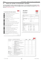
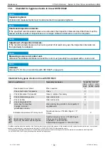
Wehaveprovidedyouwithachecklisttofacilitatestart-up.YoucanfindtheStart-upChecklist,TestRe-
portandMaintenanceChecklistonthefinalpagesofthismanualoravailabletodownloadonour
e-stulz
page at
www.stulz.de/en/e-stulz
.
TEST REPORT
STULZ GMBH
STULZ UltraSonic®
KLIMATECHNIK
Air Conditioning & Humidifying
Systems Division
Phone
+49 (0)40 55 85 252
Fax
+49 (0)40 55 01 315
KTR No.:
Testperformedby:
Date:
Customername:
Address,zipcode,city:
Order:
Contact:
Phone:
Unit type: Ultrasonic humidifier
BNB
ENS
SCA
FN
Unitname:
Serialno.:
Errormessage:
Electricalsupply:
230V/1Ph/50Hz
Comments:
Reason for test
Start-up
Service
Fault
General condition
(beforethetest)
Very good
Good
Adequate
Poor
Electrical test of humidifier
Solenoid fill valve
OK
Damaged/tight
Comments:
Oscillators
Circuit 1
OK
Damaged
Comments:
Oscillators
Circuit 2
OK
Damaged
Comments:
Fan module
OK
Damaged
Comments:
Safety chain
Low level float switch
OK
Damaged
Comments:
Supply float switch
OK
Damaged/tight
Comments:
Auxiliary relay on PCB
OK
Damaged
Comments:
Thermostat
OK
Damaged
Comments:
Watercontactloop(ENS14+18)
OK
Damaged
Comments:
Ultrasonic Humidifier
STULZ GmbH Klimatechnik
Holsteiner Chaussee 283
22457 Hamburg, Germany
Company headquarters is Hamburg
Hamburg District Court HRB 16255
VAT ID No. DE 811 207 224
Directors:J.Stulz(Chairman),
Dr. U. Görge, M. Stulz,
M. Zimmermann
Start-up Checklist for STULZ UltraSonic® Humidifiers
The
technical documentation
of all units to be started up and their accessories is to hand
All humidifiers are precisely horizontal and securely mounted
Clearances and distances have been complied with
All units are accessible and operable
All humidifiers have an upstream actuation system
The oscillator PCBs are protected from voltage peaks by a TVS diode. This must be integrated
in the control system.
The electrical wiring is correct and complies with standards
Electrical power is available
Demineralized drinking water is connected to the supply pipe of all humidifiers
All water supply and drainage pipes and the overflow are correctly connected and secured
All accessories (e.g. water treatment system, sensors, fan, …) have been correctly fitted
All pipework channels and shut-off valves are known
Drinking water is available (if reverse osmosis or an ion exchanger is used, otherwise:
demineralized drinking water is available)
Duct units are locked with the airflow
The offtake capacity can be guaranteed by the upstream water softening equipment
The minimum pressure of 0.5 bar at the humidifiers is complied with
The maximum operating pressure of 6 bar at the humidifiers is not exceeded
The conductivity specified for the application is adhered to
Sensitive components are protected from or resistant to demineralized water
The humidifiers are protected from impurities that may arise (dust, pollen, etc.)
The flush valve is installed downstream from the humidifier in the drainage pipe, and is
below the humidifier
__________________________________
Date, signature
Job to be performed
Page Procedure and maintenance interval
Date
Signature
Date
Signature
Date
Signature
OK*
OK*
OK*
Visual inspection
48 -
Tightness of connections of water-bearing parts
-
Cleanness of filter
-
Outside of unit for impurities
-
Water tank for impurities, damage, microbial growth and
corrosion
-
Humidity sensor and ventilation slots for impurities
-
Solenoid valves for deposits
Every 3 months**
☐
☐
☐
☐
☐
☐
☐
☐
☐
☐
☐
☐
☐
☐
☐
☐
☐
☐
51 -
Check oscillators for deposits
-
Check mist guide pipes for deposits
Every 6 months**
☐
☐
☐
☐
☐
☐
Leak test
48
Inspect all screw and push-in connections for leaks and a secure fit
Every 6 months**
☐
☐
☐
Clean the air filter
50
Open filter drawer, clean filter
Every 6 months**
☐
☐
☐
Clean the water tank
51
Remove housing cover and retaining plate together with mist
guide pipes (open water tank), clean and
disinfect with hydrogen peroxide solution
Every 6 months**
☐
☐
☐
☐
☐
☐
Inspect the electrical
system
52
Remove cover of control system and check electrics
Every 6 months**
☐
☐
☐
Replace float switches
55
Open water tank, remove float switch and fill valve unit
Approx. every 10,000 operating hours**
☐
☐
☐
Replace oscillators
58
Remove water tank, disconnect cables, detach oscillators
Approx. every 10,000 operating hours**
☐
☐
☐
*
Delete as applicable
**
Time intervals may be shorter in isolated cases, depending on local conditions


