ENGLISH
10
10
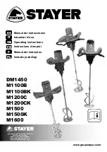
Please observe the article number on the type pl ate of your machine.
The trade names of the individual machines may vary.
Product Fea-
tures
The numbering of the product features refers to the illus
-
tration of the machine on the graphics page.
1.
Mechanical velocity selector.
2.
Auxiliary handle.
3.
Propeller stirrer
4.
Spindle motor.
5.
Switch on / off.
6.
Locking key switch on / off.
7.
Speed adjustment.
Noise/Vibration Information
Measured values determined according to EN 60745 Typi
-
cally the A-weighted noise level of the machine is: sound
pressure level 87 dB(A); sound power level 98 dB (A). Un
-
certainty K=3 dB.
Wear hearing protection!
The typical hand/arm vibration is below 2.5 m2/s
WARNING
The vibration emission level given in this
information sheet has been measured in
accordance with a standardised test given in EN 60745 and
may be used to compare one tool with another.
The vibration emission level will vary because of the ways in
which a power tool can be used and may increase above the
level given in this information sheet.
This could lead to a significant underestimate of exposure
when the tool is used regularly in such a way.
Note:
To be accurate, an estimation of the level of ex
-
posure to vibration experienced during a given period of
work should also take into account the times when the
tool is switched off and when it is running but not actually
doing the job. This may significantly reduce the exposure
level over the total working period.
Assembly
Before any work on the machine itself, pull the
mains plug.
Changing the Tool
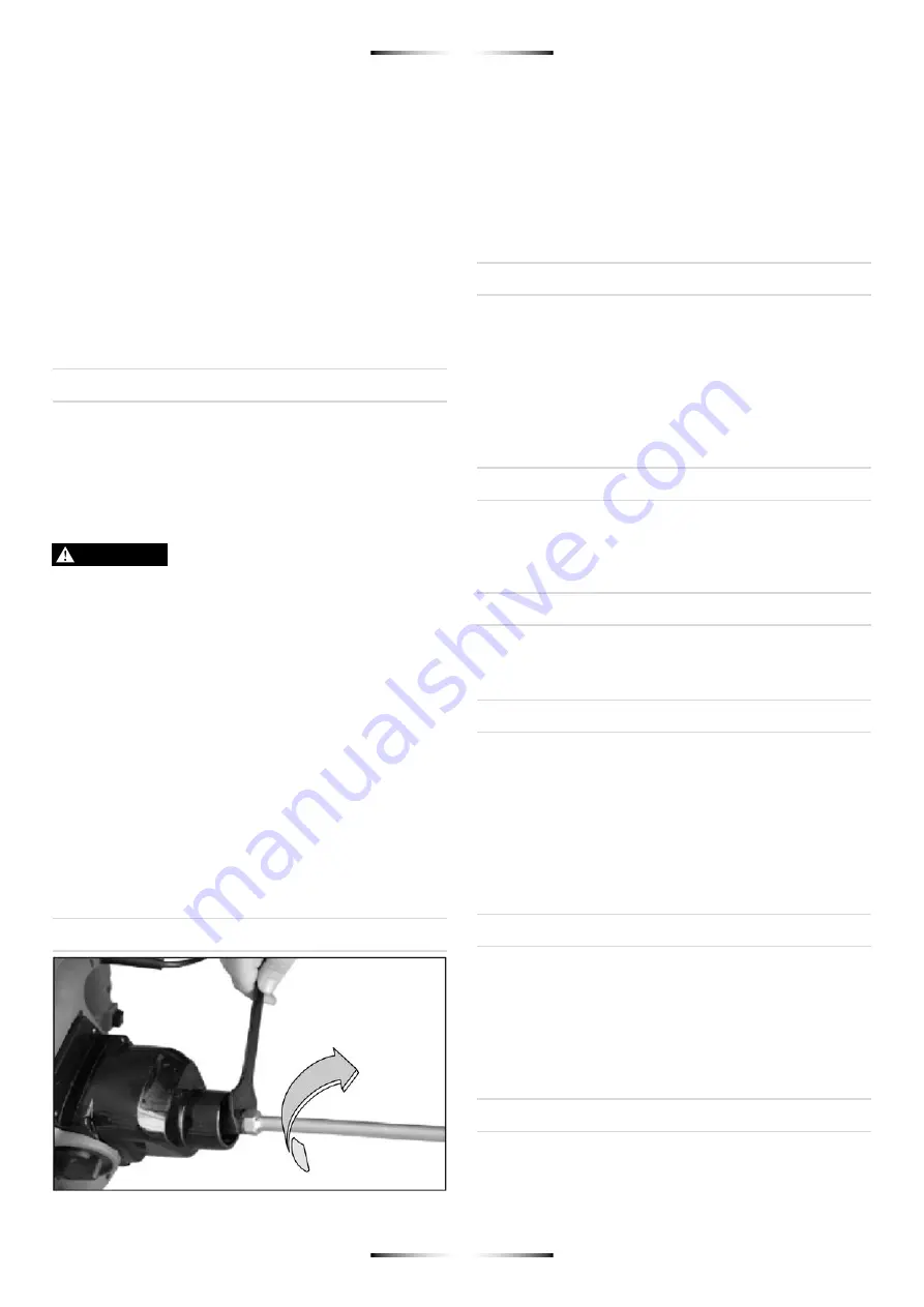
Stirrer Paddle with Male Thread, Size M14/M18 (Mod DM1450)
EScrew the stirrer paddle 3 onto the drive spindle 4
Hold the drive spindle 4 in place with an open-end
spanner (size 22 mm ) and the stirrer paddle 3
with a second open-end spanner (size 22 mm).
The stirrer paddle is disassembled in reverse order.
Operation
Operation and use
Improper use can cause damage to the tool. Please ob
-
serve the following instructions:
- only use tools up to the prescribed diameter.
- only use the tool at loads which do not reduce the
speed severely or bring the tool to a standstill.
- Check whether the data on the type plate comply with
the actual voltage of mains supply. Tools intented for
230 V. may also be connect to 220 V. / 240 V.
Fitting the mixing tool
Screw the tools with the end piece M14 x 2 as far as pos
-
sible into the tool holding fixture and tighten with the span
-
ner (22 mm.) included in the accessories.
Switching on and off
To switch the tool on, press the switch
5
and hold it down.
To switch the tool off, release the switch
5
.
Continuous operation
To switch on continuous operation:
press the switch
5
up to the stop and at the same time press the locking
button
6
. The switch 5 locks, and continuous operation is
activated.
To switch off continuous operation:
press the switch
5
again and then let go. The lock on the switch
6
is released,
and continuous operation is deactivated.
Removing tools (mixer)
Fit the flat spanner (22 mm) onto the hexagon of the tool
end piece (mixer) and turn to the left to unscrew the tool
from the spindle.
Motor electronics / Operating
motor electronics
Starting current limiting
The electronically controlled soft start ensures that the
machine starts smoothly. This also prevents spray from
thin liquids when the tool is switched on.
The lower starting current means thar a 16 A fuse is large
enough for the machine.

