


– 90 –
MAINTENANCE GUIDE
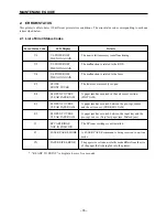
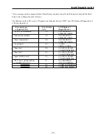
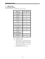
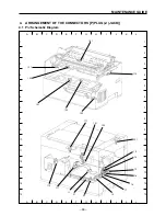
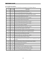
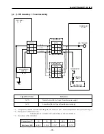
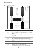
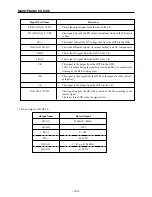
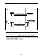
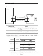
4.2 List of P/J Connectors
The coordinates of the connectors (P/J) shown below correspond to 4.1 P/J Schematic Diagram.
P/J
Coordinates
Connections
11
G12
Connects the MCU PWB to the LVPS assembly.
12
G13
Connects the MCU PWB to the ROS harness assembly.
13
H13
Connects the MCU PWB to the exit and thermistor harness assembly.
14
H13
Connects the MCU PWB to the main motor.
15
H12
Connects the MCU PWB to the HV harness assembly.
16
H13
Connects the MCU PWB to the feed solenoid.
17
H13
Connects the MCU PWB to the CRU harness assembly.
18
H13
Connects the MCU PWB to the P/H harness assembly.
31
G13
Connects the MCU PWB to Y-DEBUG.
32
G13
Connects the MCU PWB to the LED harness assembly.
111
F12
Connects the LVPS assembly to the MCU PWB.
112
D12
Connects the LVPS assembly to the AC fuser harness assembly.
114
I4
Connects the fuser assembly to the AC fuser harness assembly.
121
F5
Connects the LD to the ROS harness assembly.
122
G5
Connects the ROS motor to the ROS harness assembly.
123
H6
Connects the SOS to the ROS harness assembly.
131
D4
Connects the thermistor in the fuser assembly to the exit and thermistor harness
assembly.
132
E4
Connects the exit sensor to the exit and thermistor harness assembly.
151
F12
Connects the MCU PWB to the HVPS.
152
F11
Connects the HVPS to the fan.
171
E11
Connects the CRU sensor to the CRU harness assembly.
181
F3
Connects the pre-regi. sensor to the P/H harness assembly.
321
I10
Connects the LED PWB to the LED harness assembly.
Содержание WinType 4000
Страница 1: ...WinType 4000 TECHNICAL MANUAL SECOND EDITION LASER PRINTER ...
Страница 4: ......
Страница 6: ... 2 GENERAL SPECIFICATIONS ...
Страница 14: ... 10 THEORY OF OPERATION ...
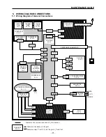
Страница 26: ... 22 THEORY OF OPERATION Figure 2 9 Electrical ...
Страница 28: ... 24 REPLACEMENT AND ADJUSTMENT OF PARTS ...
Страница 62: ... 58 REPLACEMENT AND ADJUSTMENT OF PARTS ...
Страница 64: ... 60 MAINTENANCE GUIDE ...
Страница 111: ... 107 MAINTENANCE GUIDE Direction the paper is fed through the printer H G F 3 Skew 2 0mm E 2 0mm E F G H 245mm ...
Страница 114: ... 110 MAINTENANCE GUIDE ...
Страница 116: ... 112 TROUBLESHOOTING ...
Страница 176: ... 172 5 ELECTRICAL 5 1 Disassembly Drawing 1 2 3 4 14 4 14 2 14 1 14 3 13 12 11 6 5 7 8 9 10 ...
Страница 179: ......


