


– 21 –
THEORY OF OPERATION
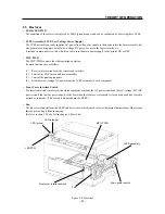
3.5 Electrical
• LED & LED PWB
The condition of the printer is displayed by LEDs (green/orange) and can be confirmed by observing these LEDs.
• LVPS Assembly (LVPS: Low Voltage Power Supply)
The LVPS assembly not only supplies AC power from the power supply to the heater rod in the fuser assembly, but
also generates and supplies a stable low-voltage DC power for use in the logic circuitry, etc.
It includes a main power switch which is used to turn the main power supply to the printer ON or OFF.
• MCU PWB
The MCU PWB controls the whole printing operation.
Its main functions are as follows:
(1)
Receive information from the sensors and switches
(2)
Control the ROS, fuser and drive assemblies
(3)
Control the printing sequence
(4)
Distribute low-voltage DC power from the LVPS assembly to each component
• Front Cover Interlock Switch
The interlock switch is a safety switch which completes or breaks the AC power circuit and the low-voltage (24V) DC
power circuit (but not the power supply to the fan) when the front cover assembly is closed or opened (the switch is
pressed or released). (This switch is mounted onto the HVPS.)
• Fan
The fan receives power from the HVPS and draws in air which is used to lower the internal temperature of the system,
thereby preventing it from increasing.
(Refer to section 1.2 Parts List in chapter 6, Parts List.)
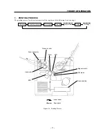
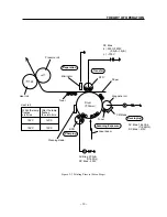
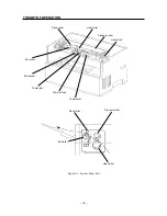
Figure 2-8 Electrical
LVPS assembly
Main power switch
Front cover Interlock switch
LED PCW
MCU PWB
LED (orange)
LED (green)
Fan
Содержание WinType 4000
Страница 1: ...WinType 4000 TECHNICAL MANUAL SECOND EDITION LASER PRINTER ...
Страница 4: ......
Страница 6: ... 2 GENERAL SPECIFICATIONS ...
Страница 14: ... 10 THEORY OF OPERATION ...
Страница 26: ... 22 THEORY OF OPERATION Figure 2 9 Electrical ...
Страница 28: ... 24 REPLACEMENT AND ADJUSTMENT OF PARTS ...
Страница 62: ... 58 REPLACEMENT AND ADJUSTMENT OF PARTS ...
Страница 64: ... 60 MAINTENANCE GUIDE ...
Страница 111: ... 107 MAINTENANCE GUIDE Direction the paper is fed through the printer H G F 3 Skew 2 0mm E 2 0mm E F G H 245mm ...
Страница 114: ... 110 MAINTENANCE GUIDE ...
Страница 116: ... 112 TROUBLESHOOTING ...
Страница 176: ... 172 5 ELECTRICAL 5 1 Disassembly Drawing 1 2 3 4 14 4 14 2 14 1 14 3 13 12 11 6 5 7 8 9 10 ...
Страница 179: ......


