


– 123 –
TROUBLESHOOTING
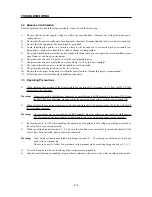
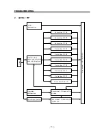
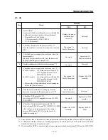
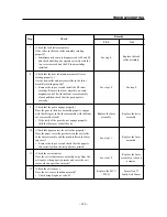
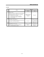
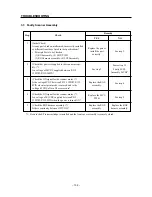
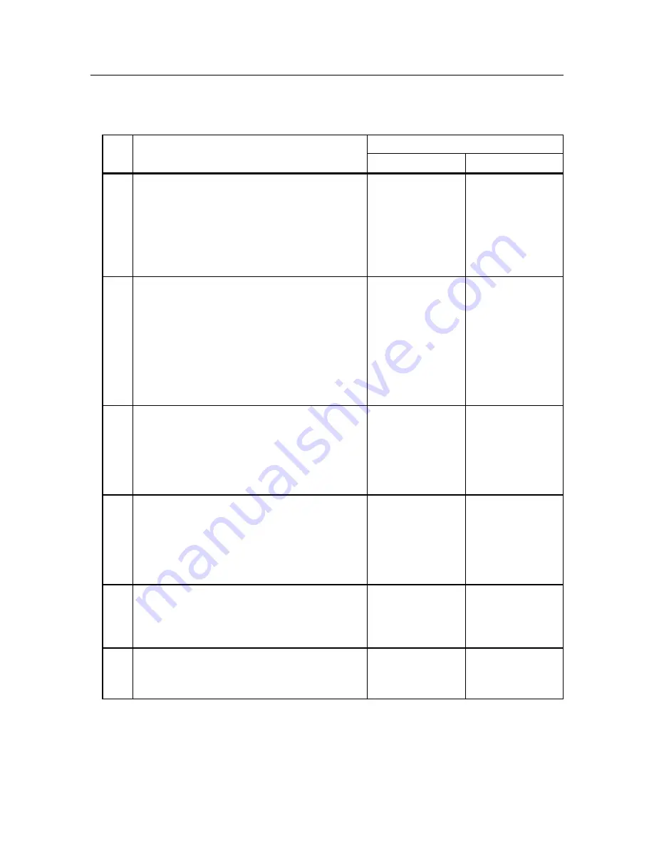
See step 8.
Replace the feed
roller assembly.
See step 10.
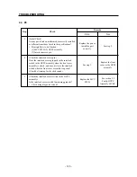
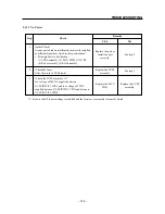
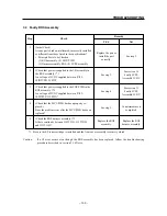
See step 9.
Replace the fuser
assembly.
Replace the drive
assembly.
Replace the fuser
assembly.
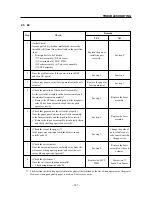
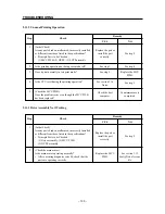
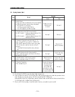
See step 11.
Replace the fuser
assembly or the exit
actuator.
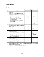
See step 12.
Replace the MCU
PWB.
See section 3.7
Faulty Exit Sensor.
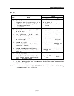
Step
Check
Remedy
YES
NO
7
(Check the feed roller assembly.)
Is the roller in the feed roller assembly rotating
properly?
• Simultaneously execute diagnosis codes 80 and 90
and check that the parts operate correctly with the
top cover removed and the EP toner cartridge
installed.
8
(Check that the heat roller and pressure roller are
rotating properly.)
Are the heat roller and pressure roller in the fuser
assembly rotating properly?
• Remove the top cover and install the EP toner
cartridge. Remove the fuser assembly, execute
diagnosis code 90 with the front cover assembly
closed and then check that the parts operate
correctly.
9
(Check that the gears engage properly.)
Does the gear in the drive assembly properly engage
with the idler gear in the fuser assembly with the front
cover assembly closed?
• If the teeth of the gears do not engage properly,
shift the idler gear so that they do.
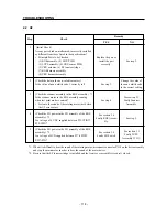
10
(Check that paper enters the exit roller properly.)
Does the paper correctly pass between the exit roller
in the fuser assembly and the pinch roller in the fuser
top cover?
• Remove the top cover and check that the paper is
fed correctly when the test pattern is printed.
11
(Check the exit actuator.)
Does the exit actuator move smoothly away from the
exit sensor when paper is present and cover the exit
sensor when paper is not present?
12
(Check the exit sensor.)
Does the exit sensor function normally?
• Check using diagnosis code 02.
Содержание WinType 4000
Страница 1: ...WinType 4000 TECHNICAL MANUAL SECOND EDITION LASER PRINTER ...
Страница 4: ......
Страница 6: ... 2 GENERAL SPECIFICATIONS ...
Страница 14: ... 10 THEORY OF OPERATION ...
Страница 26: ... 22 THEORY OF OPERATION Figure 2 9 Electrical ...
Страница 28: ... 24 REPLACEMENT AND ADJUSTMENT OF PARTS ...
Страница 62: ... 58 REPLACEMENT AND ADJUSTMENT OF PARTS ...
Страница 64: ... 60 MAINTENANCE GUIDE ...
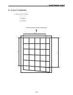
Страница 111: ... 107 MAINTENANCE GUIDE Direction the paper is fed through the printer H G F 3 Skew 2 0mm E 2 0mm E F G H 245mm ...
Страница 114: ... 110 MAINTENANCE GUIDE ...
Страница 116: ... 112 TROUBLESHOOTING ...
Страница 176: ... 172 5 ELECTRICAL 5 1 Disassembly Drawing 1 2 3 4 14 4 14 2 14 1 14 3 13 12 11 6 5 7 8 9 10 ...
Страница 179: ......


