18
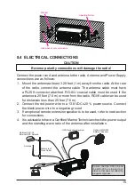
8.5.4 GPS Input - optional SCU-31 External GPS Antenna
12 V Battery
Radio Wires
Yellow: NMEA IN(
+
)
Green: NMEA IN(
−
)
Brown
Black
External GPS Antenna
SCU-31
Black
(
−
)
(
+
)
Red
2A Fuse
The
SCU-31
External GPS antenna (Built-in GPS receiver) is supplied with
49 feet (15 m) of cable and a connector. To connect the
SCU-31
to the trans-
ceiver, cut off the 6 pins antenna connector, strip the white insulation to expose
the Red, Black and Brown wires and connect as shown in the diagram. All
other wires are not used and may be cut off. The 2 amp fuse is not included.
8.5.5 Connection to External Speaker
External Speaker
Shield
White
Wire Color/Description
Connection Examples
White: External Speaker (+)
Positive wire of external 4 Ohm External speaker
Shield: External Speaker (−)
Negative wire of external 4 Ohm External speaker
8.5.6 Connecting the SCU-38 External GPS Antenna to the Radio
(GX1400GPS and GX1400GPS/E only)
Installed the SCU-38 in a location where the structure does not interfere with
the signal, it will have better performance than the internal GPS antenna.
Connect the
SCU-38
cable to the
GPS ANT
connector (Coaxial connector) on the rear
panel, then tighten the cable nut (see illustra-
tion at the right).
NOTE
: The
SCU-38
External GPS Antenna is
always used preferentially than the internal GPS
antenna.
Содержание ECLIPSE
Страница 96: ......

