© 2014 SPX CORPORATION
13
Form No. 1000773
Rev. 0 August 12, 2014
GENERAL OVERVIEW
(Detailed setup, start up and Operating Instructions begin on page 20)
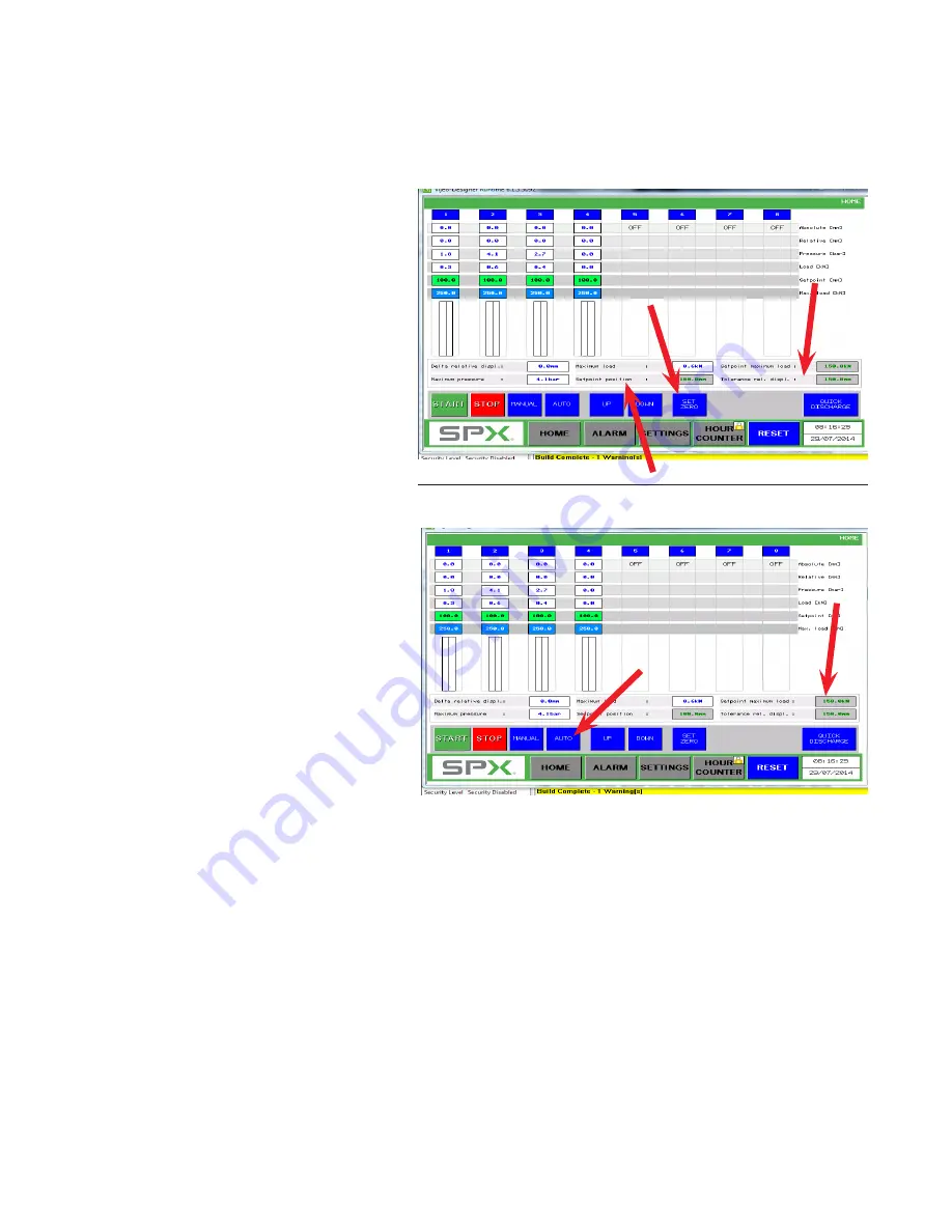
• On the HMI touch screen, push the
“Set Zero” button to set the read
-
ings of all displacement sensors to
“Forced Zero” This defines the start
-
ing point of the synchronized move
-
ment.
• Enter the allowed maximum differ
-
ence between the leading and the
lagging lift point (Tolerance Rel.
Displ.). Make sure you observe the
unit-setting you have chosen earlier.
Enter the target stroke all lift points
shall reach simultaneously under
"Setpoint Position".
•
IMPORTANT:
As a background
safety-check, the system will
continuously monitor the pressure in
each cylinder and compare it to a
pre-set maximum pressure value.
Enter this max pressure value per
cylinder. This value shall be calcu
-
lated based on the cylinder capacity
and the expected / predicted load at
the referring Lifting point.
• On the HMI, set the operation mode
to “Auto”.
NOTE:
It is suggested that for the first run, the duration
"ON"
be set at 40 ms, the duration
"OFF"
be set at 20 to 30 ms, and the release quick discharge pressure be set at 50 bar.
• As you select each cylinder, you will be required to input data for each of the cylinder’s rela
-
tive to pressure at 4 and 20 mAmps, and maximum load and maximum pressure.
• Back on the home screen, you must set the parameters of set point position, set point maxi
-
mum load, and tolerance for relative displacement. The set point position target has to be
greater than the relative position of the cylinder’s in order to move the load up or down.
NOTE:
For the first test of lifting the platform, set the set point target at 25 mm. Before
performing lift, manually measure the platform height at each active cylinder. Record the
data for each cylinder.


