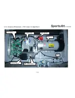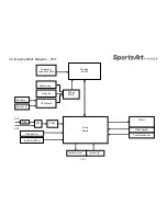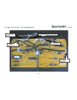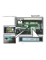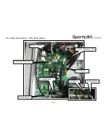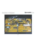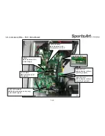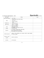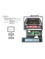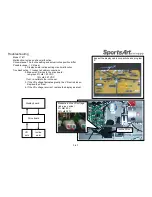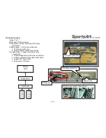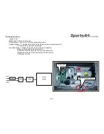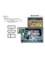
2-1. Electronic Malfunction Troubleshooting Table – T611
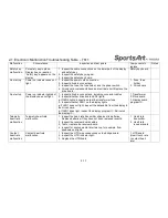
Malfunction
Circumstance
Inspection and test points
Components to
replace
Notes
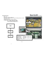
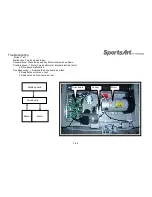
ERR 7
ERR7 appears at startup.
1. Inspect the incline VR cable connection.
2. Usually ERR7 indicates the display is stuck at either the highest
or lowest position.
3. Inspect whether LED5 and LED6 light on the drive board. If lit,
the display or cable malfunction may be causing a malfunction.
4. Inspect whether the drive board emits voltage to the incline
motor. If not, replace the drive board.
5. Recalibrate the incline set or replace the incline set as a test.
1.VR
2. Drive board
SERVICE
REQUIRED…
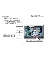
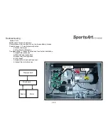
Display shows “SERVICE
REQUIRED TREADMILL
SHUTTING DOWN
STOPPING
1. Inspect the motor thermal switch wire connection and the LED4
M-TEMP on the drive board. Feel the motor. Is it hot?
2. If the motor is hot and the unit has been in use, turn off the unit.
Let the unit rest one half hour or more. Then turn off the unit.
3.The running belt and deck need to lubrication.
4.Inspect the running belt and deck.
5.if necessary , replace the running belt.
6. If steps above do not solve the problem, replace the motor.
1.Running belt
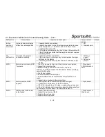
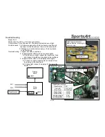
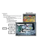
Main fuse is
broken.
Turn on unit. The fuse
blows.
1. Inspect whether the power cord has an electrical short.
2. Drive board components have an electrical short. Replace the
drive board.
1. Drive board
Main fuse is
broken.
Press the speed up key. The
motor start up fuse blows.
1. Inspect the motor for abnormalities.
2. Replace the drive board.
3. Replace the motor.
1. Motor
2. Drive board
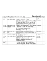
Main fuse is
broken.
In use, the main fuse blows. 1. Inspect whether the main power voltage is too low. Normal is
110V or 220V +- 10%.
2. Inspect whether the walk belt is too tight.
3. Inspect the walk belt for wear. Lubricate or replace it.
4. Inspect the condition of the fuse holder and fuse.
5. Replace the drive board.
6. Inspect motor brushes.
1. Walk belt
2. Drive belt
3. Drive board
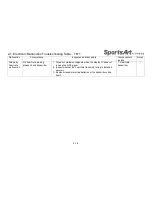
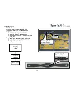
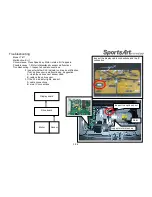
Show total
distance
Do not put the safety key in place. Press and hold the
<CHANGE> key for three seconds. The program IC version,
metric/imperial unit selection, total distance, total time ,and user
id on/off setting appear.
2-1-3
Содержание T611
Страница 1: ...T611 Repair Manual Electronics...
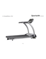
Страница 4: ...1 1 Product Picture T611 1 1 1...
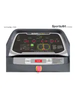
Страница 5: ...1 2 Overlay T611 1 2 1...
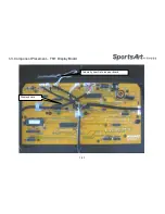
Страница 6: ...1 3 Component Placement T611 Display Board 1 3 1 Display board Telemetry heart rate receiver board...
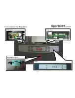
Страница 7: ...1 3 Connections T611 Bridge Board 1 3 2 To Safety key board HTR board Soft key Bridge board...
Страница 11: ...1 5 Connections T611 Bridge Board 1 5 2 To Safetykey board To HTR board To Display...
Страница 13: ...1 6 LED Indicators T611 Display Board 1 6 1 LED1 power indicator Lit indicates 5 VDC power supply...

