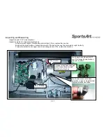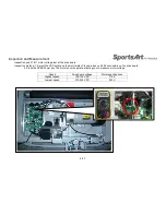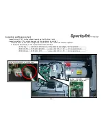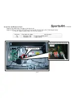
Inspection and Measurement
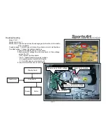
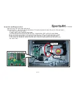
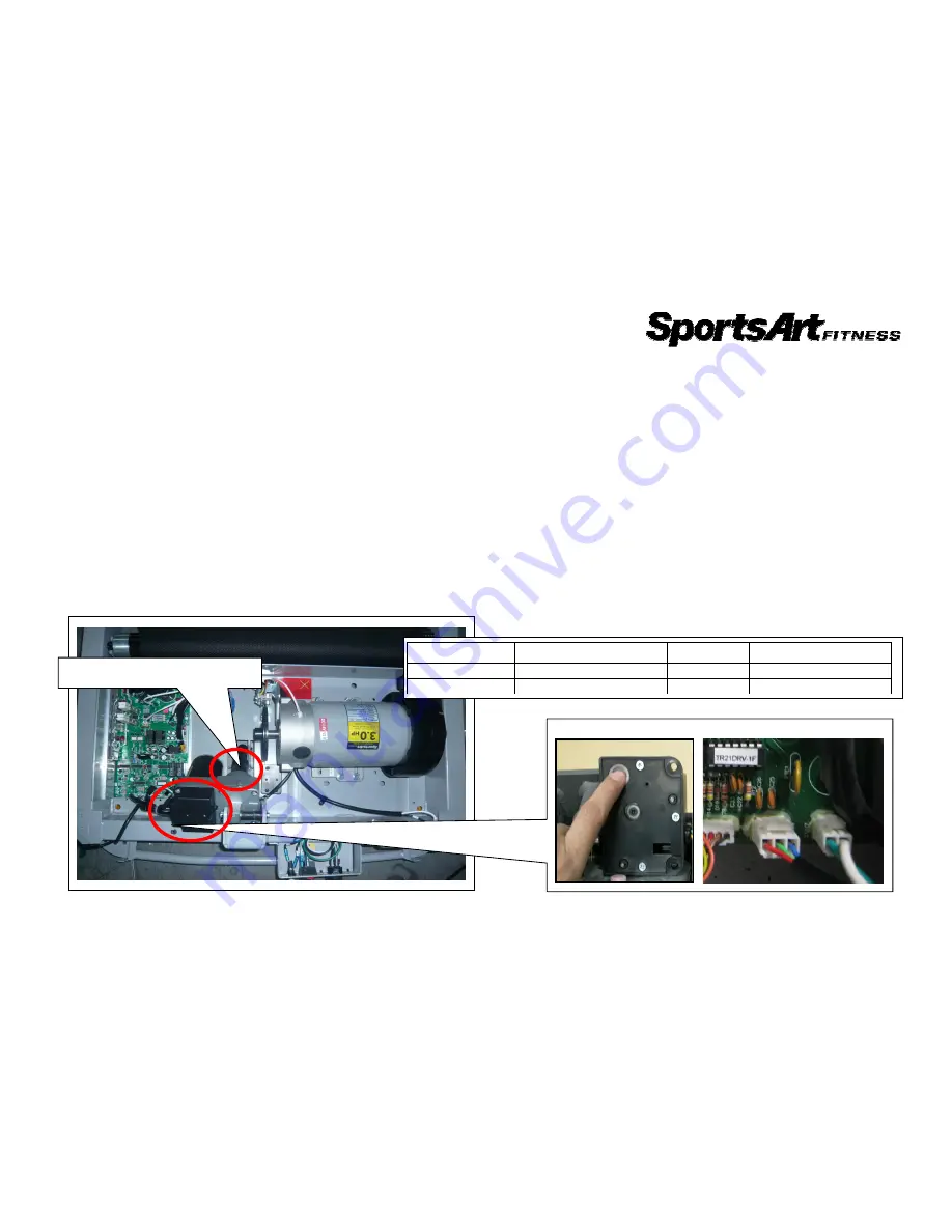
Inspection point: Incline motor and VR calibration
Inspection method: I. Calibration goals
Adjust the incline set tube to the red calibration line. Adjust the VR voltage across red
and green wires to 1.20V.
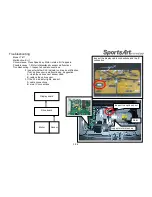
II. Calibration steps:
Step 1. Adjust the incline tube to the red calibration line as follows:
A. Remove VR set screws. Remove the VR cap.
B. Rotate the VR to set voltage across red and green wires to 2.5V.
C. Press the INCLINE<
▲
>/<
▼
> keys to operate the incline up or down, making the incline
tube return to the red calibration line.
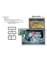
Step 2. Adjust the VR voltage across red and green wires to 1.20V.
A. Rotate the VR to set voltage across red and green wires to 1.20V.
B. Use screws to secure the VR cap back into place.
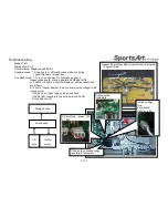
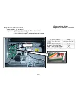
Step 3. When calibration is complete, test incline operation as follows.
A. Press the Incline<
▲
> key. The incline should operate to 15%. Measure incline VR voltage.
It should be 3.57V.
B. Press the Incline<
▼
> key. The incline should operate to 0%. Measure incline VR voltage.
It should be 1.20V.
4-7-1
Incline red calibration line
VR voltage adjustment
Incline position
Incline set
Incline VR
Treadmill position
0%
At red calibration line
1.20V
Level position
15%
At longest point
3.57V
Highest position
Содержание T611
Страница 1: ...T611 Repair Manual Electronics...
Страница 4: ...1 1 Product Picture T611 1 1 1...
Страница 5: ...1 2 Overlay T611 1 2 1...
Страница 6: ...1 3 Component Placement T611 Display Board 1 3 1 Display board Telemetry heart rate receiver board...
Страница 7: ...1 3 Connections T611 Bridge Board 1 3 2 To Safety key board HTR board Soft key Bridge board...
Страница 11: ...1 5 Connections T611 Bridge Board 1 5 2 To Safetykey board To HTR board To Display...
Страница 13: ...1 6 LED Indicators T611 Display Board 1 6 1 LED1 power indicator Lit indicates 5 VDC power supply...

