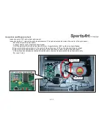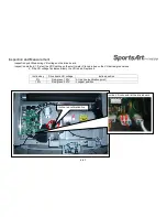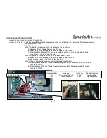
Inspection and Measurement
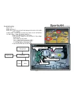
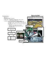
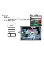
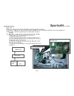
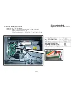
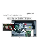
Inspection point: Measuring VR voltage on the drive board
Inspection method: 1. Select the VDC setting on the multi-meter. Place probes on the VR set red-green wires.
2. If the VR voltage fluctuates widely, the VR is bad. Replace it.
4-6-1
Incline key
Drive board VR voltage
Incline position
0%
Red-green 1.20V
At red line (calibration point)
15%
Red-green 3.57V
Longest position
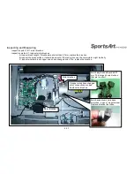
Incline VR connector at the drive board
Incline red calibration line
Содержание T611
Страница 1: ...T611 Repair Manual Electronics...
Страница 4: ...1 1 Product Picture T611 1 1 1...
Страница 5: ...1 2 Overlay T611 1 2 1...
Страница 6: ...1 3 Component Placement T611 Display Board 1 3 1 Display board Telemetry heart rate receiver board...
Страница 7: ...1 3 Connections T611 Bridge Board 1 3 2 To Safety key board HTR board Soft key Bridge board...
Страница 11: ...1 5 Connections T611 Bridge Board 1 5 2 To Safetykey board To HTR board To Display...
Страница 13: ...1 6 LED Indicators T611 Display Board 1 6 1 LED1 power indicator Lit indicates 5 VDC power supply...

