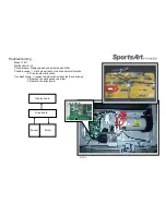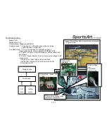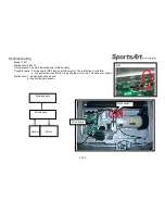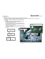
Inspection and Measurement
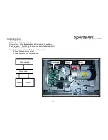
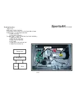
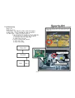
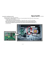
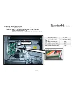
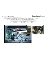
Inspection point: T611 incline voltage measurement at the drive board
Inspection method: 1. Do not press any key. Incline indicators do not light.
The drive board does not emit voltage to the incline motor. The incline motor does not operate.
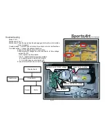
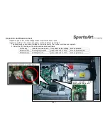
2. Select the VDC setting on the multi-meter and test as follows.
4-5-1
Incline key
Indicator on drive board
Drive board incline voltage Incline operation
INCLINE <
▼
>
LED5 lights (DOWN)
green-white +40 or -40V
Incline operates down
INCLINE <
▲
>
LED6 lights (UP)
green-white +40 or -40V
Incline operates up
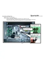
Incline
indicators
(LED5
LED6) on the drive board
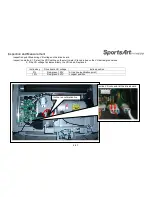
I
ncline motor connection on drive board
Содержание T611
Страница 1: ...T611 Repair Manual Electronics...
Страница 4: ...1 1 Product Picture T611 1 1 1...
Страница 5: ...1 2 Overlay T611 1 2 1...
Страница 6: ...1 3 Component Placement T611 Display Board 1 3 1 Display board Telemetry heart rate receiver board...
Страница 7: ...1 3 Connections T611 Bridge Board 1 3 2 To Safety key board HTR board Soft key Bridge board...
Страница 11: ...1 5 Connections T611 Bridge Board 1 5 2 To Safetykey board To HTR board To Display...
Страница 13: ...1 6 LED Indicators T611 Display Board 1 6 1 LED1 power indicator Lit indicates 5 VDC power supply...

