TRAK Machine Tools
Southwestern Industries, Inc.
The ProtoTRAK DXF Converter Operating Manual
35
Avoid Non-Supported Drawing Objects
Only lines, arcs and circles can be converted into ProtoTRAK events. Using more complicated
geometries like splines, or polylines, will cause the converter to break these entities down into
lines and arcs that it can recognize. This may result in a longer waiting time while your drawing is
being processed.
Avoid Large Gaps
Try to eliminate large gaps in your drawings. It is possible to slightly shift geometry when gaps
are closed through the PT4 Converter process.
Edit Geometry to Accommodate Your Tool
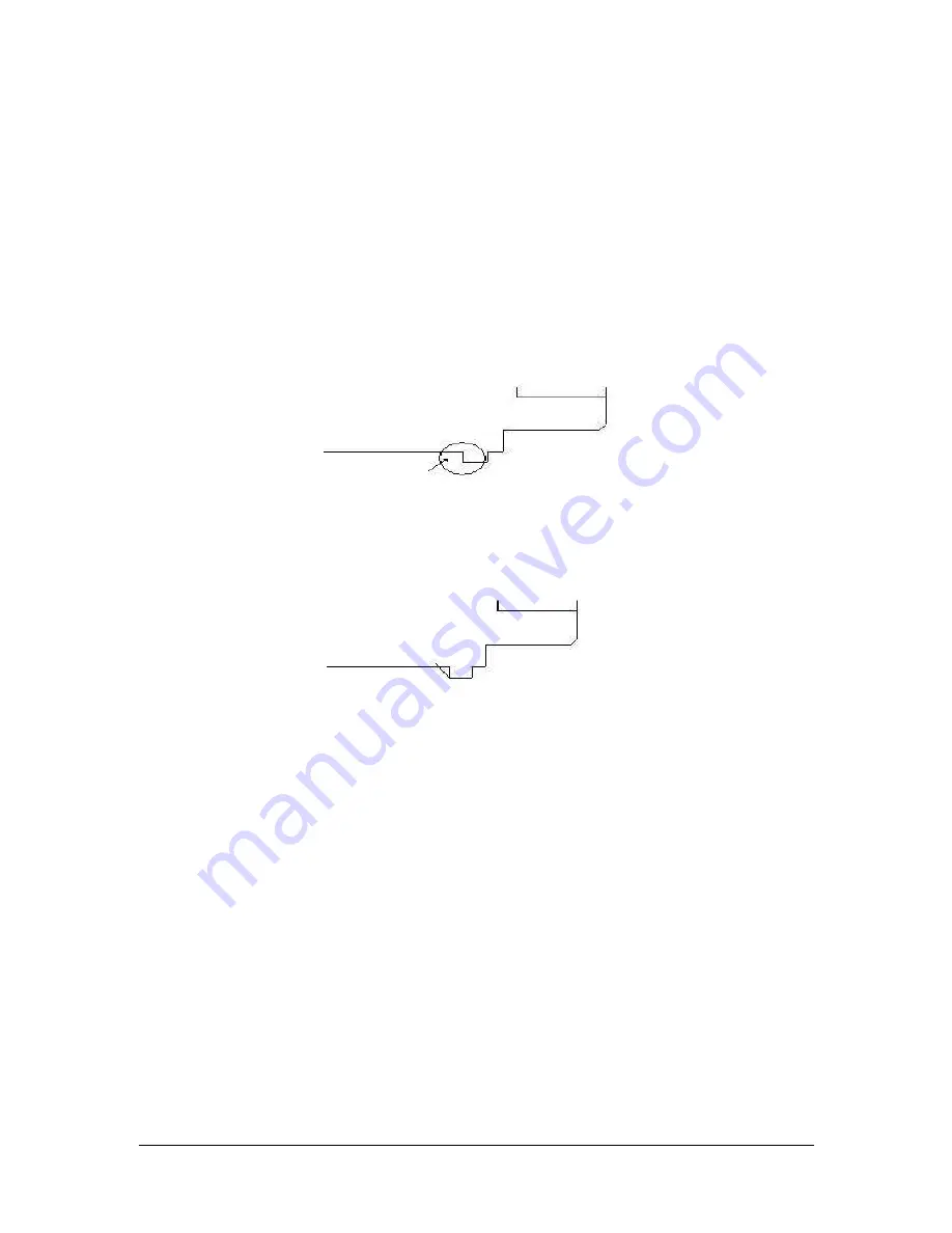
In the drawing below, it would be desirable to machine most of the material in one operation
using one tool with the powerful Cycle routine. A right-hand turn/face tool would be the best for
most of the geometry, but clearly won’t work for the last sharp corner to the left.
In this case, use the New Point feature and create a new line for a profile. The objective is to
create a geometry that your right-hand turn/face tool can handle. After roughing the material,
you can machine that last corner in a separate operation with a different tool.
Creating New Intersection Points
The valuable chaining feature of the cycle event uses points of intersection to tell where one line
ends and a different line begins. When you add a line using the New Point feature as in Section
5.8 above, the drawing file does not yet contain an intersection at the point the lines cross. The
reason for this has to do with the way drawing files are created. It could be a show-stopper for
using the cycle event in these cases, except that we can easily establish the intersection with a
simple trick using the Hide Line feature (you may want to review how this feature works in
section 4.7.3).
In the example above, we added a line that made sense for the right-hand turn/face tool we are
planning to use to do our roughing.
At this point, the problem is that the chaining feature will not recognize the intersection point
where our new line crosses the original line. We can make it recognize it by hiding part of the
original line, and then undoing this so that our original line will be preserved for machining later.
To see how this works, consider the example below. First, we select the Hide Line button. Then,
we select the original line that crosses the line that we added.


