-4-
For Machines Mfd. Since 12/21
South Bend Tools
Model SB1007
I N T R O D U C T I O N
Untrained users have an increased risk of
seriously injuring themselves with this lathe.
Do not operate this lathe until you have
understood this entire manual and received
proper training.
Controls & Components
Refer to Figures 3–7 and the following
descriptions to become familiar with the basic
controls and components used to operate this
lathe.
Headstock & Quick-Change
Gearbox
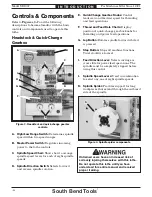
E. Quick-Change Gearbox Knobs:
Control
leadscrew and feed rod speed for threading
and feed operations.
F. Thread and Feed Rate Charts:
Display
position of quick-change gearbox knobs for
threading and power feed operations.
G. Jog Button:
Rotates spindle forward while it
is pressed.
H. Stop Button:
Stops all machine functions.
Twist clockwise to reset.
I. Feed Direction Lever:
Selects carriage or
cross slide for power feed operations. The
spindle must be completely stopped before
using this control.
J. Spindle Speed Levers:
Used in combination
to select any one of eight spindle speeds.
K. Spindle Spider:
Provides support for long
workpieces that extend through the outboard
side of the spindle.
Figure
Figure 3. Headstock and quick-change gearbox
. Headstock and quick-change gearbox
controls.
controls.
II
H
H
G
G
F
F
A
A
JJ
E
E
D
D
B
B
C
C
A. High/Low Range Switch:
Determines spindle
speed within two speed ranges.
B. Master Power Switch:
Regulates incoming
power to the lathe controls.
C. Spindle Speed Chart:
Shows how to arrange
spindle speed levers for each of eight spindle
speeds.
D. Spindle Direction Switch:
Selects forward
and reverse spindle rotation.
Figure
Figure 4. Spindle spider components.
Spindle spider components.
K
K
Содержание SB1007
Страница 84: ...southbendtools com Printed In U S A MN16349...


