— 26 —
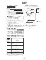
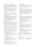
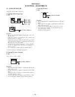
Key matrix test
JOG shuttle test
LCD test
LED OFF
1) Press the One-Touch B key and turn off the LCD
Backlight LED. (CID/LCD)
2) Press the One-Touch B key and turn off the DIAL
LED. (CID/LCD)
3) Press the One-Touch B key and turn on all LEDs
and return to step 1. (CID/LCD)
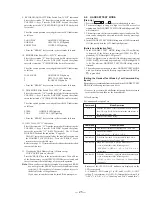
Command
Mode/Operation
5-1-#
5-2-#
5-3-#
5-4-#
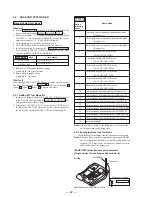
E) MMI Test
Note:
In the loopback test, the sound route of the handset is set to
the normal TALK state (Set Mic-in and SPKO to be effec
tive).
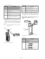
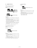
[Handset AUDIO Input/Output Level Measurement
[CODEC Forward Loopback (L1); 3-1-#]]
Setting:
Command
Mode/Operation
CODEC Forward Loopback (L1)
(MIC
n
SP) (within CODEC)
ADPCM Forward Loopback (L2)
(MIC
n
CODEC
n
ADPCM
n
CODEC
n
SP)
ADPCM
n
RF Loopback (MIC
n
CODEC
n
ADPCM
n
RF
n
ADPCM
n
CODEC
n
SP)
3-1-#
3-2-#
3-3-#
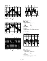
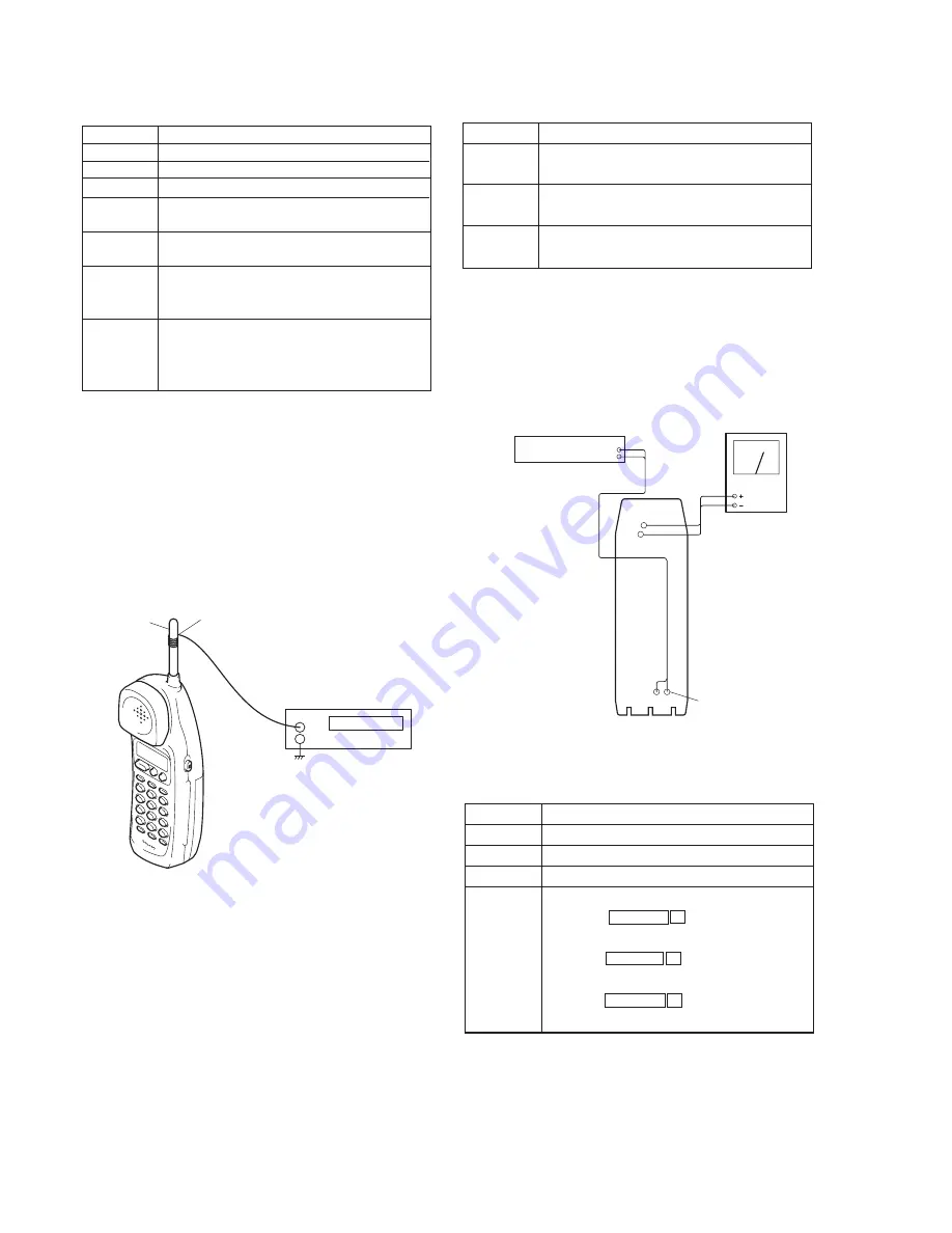
Audio analyzer
Level meter
Hand main board (conductor side)
TP601
TP603
TP604
TP602
Setting: OSC=–41dBV
(Open terminal)
MOD=1kHz
osc out
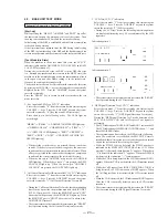
Setting:
Specified Values: 904.2 MHz ± 27kHz
Command
Mode/Operation
One channel continuous send (TX power: HIGH)
One channel continuous send (TX power: Medium)
One channel continuous send (TX power: Low)
One channel continuous send (TX power: High,
Spread code = 0)
Channel increment.
2 ch
n
3 ch
n
... 20 ch
n
1 ch
n
...
When the PGM button is pressed, the spread code is set.
600 kHz
n
300 kHz
n
200 kHz
n
100 kHz
n
0
n
Normal increments
When the One-ouch C is pressed while the internal data
is set, it increments in the following order.
All 0’s
n
All 1’s
n
Counts up
n
Counts down
increments.
2-1-#
2-2-#
2-3-#
2-4-#
*
PGM
One-touch C
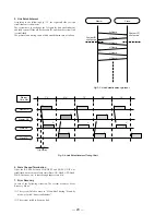
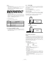
C) Continuous Transmission Test
Note:
In the continuous transmission test, the “All 0’s Data” in
ASIC should be used.
Statuses of the CH, spread code, AGC and data are displayed on the LCD
respectively
C: Channel, S: Spread code setting (6 is 600 kHz setting, 3 is 300 kHz
setting, 2 is 200 kHz setting, 1 is 100 kHz setting, 0 is 0 (no spread) and
N is Normal), A: AGC setting (7 is maximum, 0 is OFF), D: Internal data
setting (0 is “All 0’s”, 1 is “All 1’s”, U is “Counts up” and D is “Counts
down”).
Specified Values: -27.5 to -23.5 dBV
Pickup coil
Frequency counter
ANTENNA
+
–
D) Loopback Test
Содержание SPP-A9171 - Cordless Telephone With Answering Machine
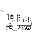
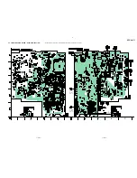
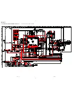
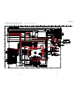
Страница 38: ...SPP A9171 41 42 6 4 SCHEMATIC DIAGRAM BASE MAIN SECTION 1 2 See page 33 for Note on Schematic Diagrams ...
Страница 39: ...SPP A9171 43 44 6 5 SCHEMATIC DIAGRAM BASE MAIN SECTION 2 2 See page 33 for Note on Schematic Diagrams ...
Страница 41: ...SPP A9171 47 48 6 7 SCHEMATIC DIAGRAM BASE KEY SECTION See page 33 for Note on Schematic Diagrams ...
Страница 43: ...SPP A9171 51 52 6 9 SCHEMATIC DIAGRAM DISPLAY SECTION See page 33 for Note on Schematic Diagrams ...
Страница 45: ...SPP A9171 55 56 6 11 SCHEMATIC DIAGRAM HAND MAIN SECTION See page 33 for Note on Schematic Diagrams ...

