— 22 —
4-2.
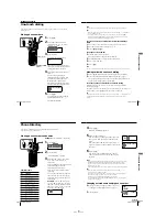
BASE UNIT TEST MODE B
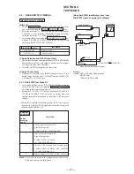
Manual System Test Mode
[Start-up]
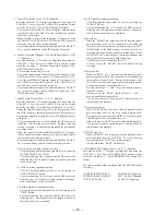
1. Set the DIAL MODE switch to T (TONE), and turn on the
power while pressing the MEMO ANSWER BOX3 key.
2. Select the test mode “11” from the test mode idle state using the
/– keys. Press the “ANSWER” key and the system
enters the test mode “11” [TEST MODE idling B].
3. After stating up. Test Mode B, perform dial test.
4. The TEST MODE B state will be set after the dial test.
5. In test mode idling B, pressing the HANDSET LOCATOR
key with the P (PULSE)/T (TONE) switch set to T (TONE) state
switches to BASE UNIT TEST MODE B-1.
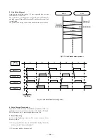
[Dial Test]
After starting BASE UNIT TEST Mode A, close the circuit for about
500 msec after start, and dial PAUSE , 0 (DP), wait 2 seconds, 1
(Tone), 4 (Tone), 8 (Tone), # (Tone) in this order.
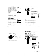
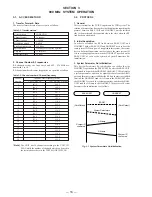
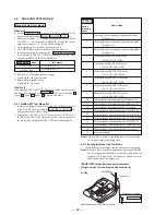
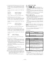
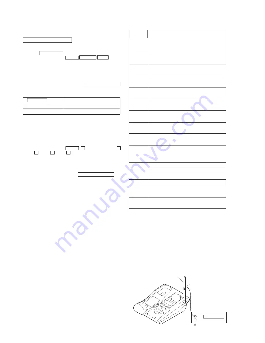
4-2-1. BASE UNIT Test Mode B-1
1. In test mode idling B with the P (PULSE)/T (TONE) switch set
to the T (TONE) state, pressing the HANDSET LOCATOR key
changes the mode as shown below.
2. Setting the P (PULSE)/T (TONE) switch from T (TONE) to P
(PULSE) in BASE UNIT test mode B-1 any time also enables
the mode to be changed to BASE UNIT test mode idling B.
HANDSET
LOCATOR
button
pressing
count
Radio mode
1ch single carrier continuous transmission mode
(high power)
10ch single carrier continuous transmission mode
(high power)
20ch single carrier continuous transmission mode
(high power)
1ch continuous RECEPTION mode
(LNAON, AGC=MIN)
1ch continuous RECEPTION mode
(LNA=ON, AGC=OFF)
10ch continuous RECEPTION mode
(LNA=ON, AGC=MIN)
10ch continuous RECEPTION mode
(LNA=ON, AGC=OFF)
20ch continuous RECEPTION mode
(LNA=ON, AGC=MIN)
20ch continuous RECEPTION mode
(LNA=ON, AGC=OFF)
1ch continuous transmission mode (high power)
1ch continuous transmission mode (middle power)
1ch continuous transmission mode (low power)
10ch continuous transmission mode (HI POWER)
10ch continuous transmission mode (MID POWER)
10ch continuous transmission mode (LOW POWER)
20ch continuous transmission mode (HI POWER)
20ch continuous transmission mode (middle power)
20ch continuous transmission mode (low power)
test mode idling B.
1
2
3
4
5
6
7
8
9
10
11
12
13
14
15
16
17
18
19
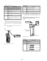
*1 Radio block: TDD mode (master timing)
Audio block: Line speech status
*2 Radio block: Standby status
Audio block: Line open
DIAL MODE switch
T (TONE) side
P (PULSE) side
Idle status
Test Mode Idle B-1 *1
Test Mode Idle B-2 *2
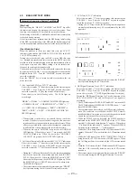
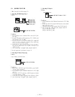
ANTENNA
Pickup coil
Frequency counter
+
–
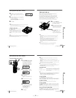
[BASE UNIT carrier frequency measurement
[Single carrier 1ch continuous transmission]]
Setting:
Note
: If the LEDs are lit due to the idling state test, clear all the
LEDs, and return to the idling state.
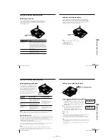
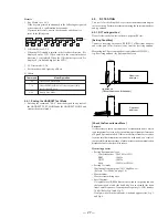
4-2-2. Ending the Base Unit Test Mode
1.
To end the base unit test mode, turn off the power of the base unit.
Note
: When you have exitted the test mode by pressing the ERASE
key, never press the ERASE key because the audio deteetion
sesitivity (VOX sensiriviry) of the answer phone is reset to
the default value of the parameter.
Specified Values: 904.2 MHz ± 27kHz
Содержание SPP-A9171 - Cordless Telephone With Answering Machine
Страница 38: ...SPP A9171 41 42 6 4 SCHEMATIC DIAGRAM BASE MAIN SECTION 1 2 See page 33 for Note on Schematic Diagrams ...
Страница 39: ...SPP A9171 43 44 6 5 SCHEMATIC DIAGRAM BASE MAIN SECTION 2 2 See page 33 for Note on Schematic Diagrams ...
Страница 41: ...SPP A9171 47 48 6 7 SCHEMATIC DIAGRAM BASE KEY SECTION See page 33 for Note on Schematic Diagrams ...
Страница 43: ...SPP A9171 51 52 6 9 SCHEMATIC DIAGRAM DISPLAY SECTION See page 33 for Note on Schematic Diagrams ...
Страница 45: ...SPP A9171 55 56 6 11 SCHEMATIC DIAGRAM HAND MAIN SECTION See page 33 for Note on Schematic Diagrams ...

