— 25 —
4-4.
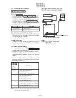
HANDSET TEST MODE
[Start-Up]
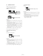
1. Press the TALK , 0 , and 1 keys simultaneously to start.
2. The normal ringer is rung at a high level for 500 msec after
starting, and The HANDSET TEST MODE and idling state LEDs
will remain lit.
3. The unit sets into the test command key input standby state. The
state can be changed to a desired test mode item by pressing a
command key.
4. In the HANDSET TEST MODE idling state, all LEDs are turned
ON (the state where the LCD backlight lights up).
[Battery Low Detection Test]
1. In the HANDSET TEST MODE idling state, if Low Battery
is detected (if the battery input terminal (IC401 Pin
&
) is
grounded), LCD Backlight LED goes off.
2. If the Low Battery state is cleared (if the battery input terminal
(IC401 Pin
&
) is released its grounding), LCD Backlight LED
is lit. The previous HANDSET TEST MODE idling state is
returned.
3. The mode cannot be changed to other HANDSET TEST MODE
with Low Battery detected (Battery input terminal (IC401 Pin
&
) is grounded.
[Setting the Handset Test Mode by Test Command Key
Inputs]
By entering test commands from the keypad in the HANDSET TEST
MODE, the following test items can be set.
• However, to set a test with a different test group, be sure to return
to test mode first and then set the desired mode.
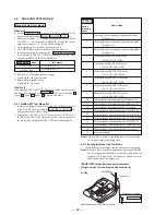
A) Test Resetting
B) Continuous Reception Test
Command
0-0-#
0-1-#
Mode/Operation
Ends the test mode. Clears the EEPROM data. Sounds
the ACK beep if OK. Exits the test mode and returns to
the normal operating state.
Returns to test mode idling.
Command
1-1-#
*
One-touch A
One-touch B
One-touch C
One channel continuous reception (LNA, AGC ON)
Channel increment.
2 ch
n
3 ch
n
... 20 ch
n
1 ch
n
...
When the One-ouch A is pressed while the LAN is
set, it toggles between ON and OFF.
When the One-ouch B is pressed while the AGC
is set, it increments in the following order.
AGC MAX
n
OFF
n
1
n
2
n
3
n
4
n
5
n
6
increments.
When the One-ouch C is pressed while the internal data
is set, it increments in the following order.
All 0’s
n
All 1’s
n
Counts up
n
Counts down
increments.
Statuses of the CH, LNA, AGC and data are displayed on the
LCD respectively
C: Channel, L: LNA setting (1 is ON and 0 is OFF), A: AGC
setting (7 is maximum, 0 is OFF), D: Internal data setting (0 is
“All 0’s”, 1 is “All 1’s”, U is “Counts up” and D is “Counts down”).
Mode/Operation
9. RECORDING QUALITY Slide Switch Test; LCD ”8” indication
Select the test mode “8” from the test mode idle state using the
/- keys. Press the “ANSWER” key and the system
enters the test mode “8” [RECORDING QUALITY Slide Switch
Test mode].
The slide switch positions are judged from the LED indications
as follows.
LONG PLAY
ANSWER LED lights up
NORMAL
NEW CALL LED lights up
SHORT PLAY
IN-USE LED lights up
• Press the “ERASE” key to return to the test mode idle state.
10. RINGER Slide Switch Test; LCD ”9” indication
Select the test mode “9” from the test mode idle state using the
/- keys. Press the “ANSWER” key and the system
enters the test mode “8” [RINGER Slide Switch Test mode].
The slide switch positions are judged from the LED indications
as follows.
TALL SAVER
ANSWER LED lights up
5
NEW CALL LED lights up
2
IN-USE LED lights up
• Press the “ERASE” key to return to the test mode idle state.
11. DIAL MODE Slide Switch Test; LCD ”10” indication
Select the test mode “10” from the test mode idle state using the
/- keys. Press the “ANSWER” key and the system
enters the test mode “10” [DIAL MODE Slide Switch Test mode].
The slide switch positions are judged from the LED indications
as follows.
PULSE
ANSWER LED lights up
TONE
NEW CALL LED lights up
• Press the “ERASE” key to return to the test mode idle state.
12. ASIC Test; LCD ”11” indication
Select the test mode “11” from the test mode idle state using the
/- keys. Press the “ANSWER” key and the system
enters the test mode “11” [ASIC Test mode]. The LCD and
MAILBOX flash and the indication “0” appears.
The ASIC test mode is controlled by the tone/pulse switch and
the HANDSET LOCATOR key. Press the “ERASE” key to
return to the test mode idle state.
Refer to the page 21, 22 test mode specifications sheet for detailed
contents of this test.
13. Clearing the Flash Memory Data (All data except
VOICE GUIDE data are cleared)
Press the “ERASE” key in the test mode idle state. Then all data
of the flash memory except VOICE GUIDE data are cleared and
the system enters the initial stage of the normal operation.
Note
: When you have exitted the test mode by pressing the ERASE
key, never press the ERASE key because the audio deteetion
sesitivity (VOX sensiriviry) of the answer phone is reset to
the default value of the parameter.
If you want to exit the test mode, turn off the main power.
Содержание SPP-A9171 - Cordless Telephone With Answering Machine
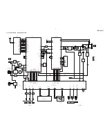
Страница 38: ...SPP A9171 41 42 6 4 SCHEMATIC DIAGRAM BASE MAIN SECTION 1 2 See page 33 for Note on Schematic Diagrams ...
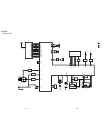
Страница 39: ...SPP A9171 43 44 6 5 SCHEMATIC DIAGRAM BASE MAIN SECTION 2 2 See page 33 for Note on Schematic Diagrams ...
Страница 41: ...SPP A9171 47 48 6 7 SCHEMATIC DIAGRAM BASE KEY SECTION See page 33 for Note on Schematic Diagrams ...
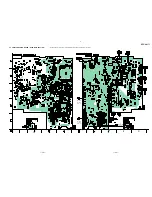
Страница 43: ...SPP A9171 51 52 6 9 SCHEMATIC DIAGRAM DISPLAY SECTION See page 33 for Note on Schematic Diagrams ...
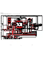
Страница 45: ...SPP A9171 55 56 6 11 SCHEMATIC DIAGRAM HAND MAIN SECTION See page 33 for Note on Schematic Diagrams ...

