— 20 —
Master
Slave
System ID
confirmed
System ID
confirmed
A-Frame
A-Frame
V-Frame
V-Frame
V-Frame
V-Frame
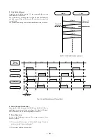
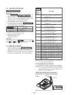
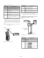
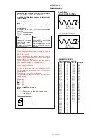
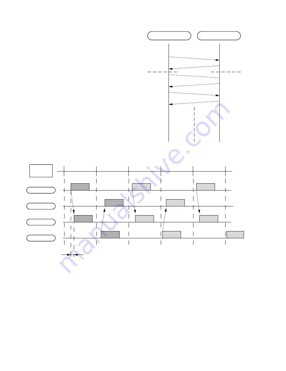
5. Link Establishment
According to the following Fig. 3-1, the requested side for link
establishment is the master.
The system have to exchange the A-Frame for link establishment,
and each system ID should be the same ID, and then the system link
is established.
The protocol and timing chart of link establishment are as follows.
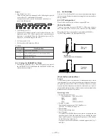
Fig. 3-3. Link Establishment protocol
Master TX
Master RX
Slave RX
Slave TX
Master
Time Slot
Trip Delay
TX
RX
TX
RX
TX
A
V
A'
V
V
V
V
A
V
A'
V
Fig. 3-4. Link Establishment Timing Chart
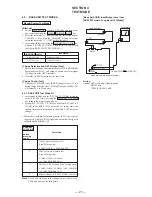
6. State Change/Tarmination
After the RF link between HANDSET and BASE UNIT was
established, a movement of each state (State: ON-Hook, OFF-Hook,
PAGE, Intercom, etc) is sent through supervisory bits.
7. Error Recovery
In case of the following situation, The system becomes “Error
Recovery Mode”.
(1) The system failed to move to “Heart-Beat” during “Stand-by
mode, or failed “link establishment”.
(2) The system failed to keep the link.
Содержание SPP-A9171 - Cordless Telephone With Answering Machine
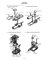
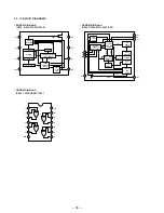
Страница 38: ...SPP A9171 41 42 6 4 SCHEMATIC DIAGRAM BASE MAIN SECTION 1 2 See page 33 for Note on Schematic Diagrams ...
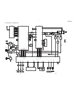
Страница 39: ...SPP A9171 43 44 6 5 SCHEMATIC DIAGRAM BASE MAIN SECTION 2 2 See page 33 for Note on Schematic Diagrams ...
Страница 41: ...SPP A9171 47 48 6 7 SCHEMATIC DIAGRAM BASE KEY SECTION See page 33 for Note on Schematic Diagrams ...
Страница 43: ...SPP A9171 51 52 6 9 SCHEMATIC DIAGRAM DISPLAY SECTION See page 33 for Note on Schematic Diagrams ...
Страница 45: ...SPP A9171 55 56 6 11 SCHEMATIC DIAGRAM HAND MAIN SECTION See page 33 for Note on Schematic Diagrams ...


