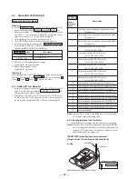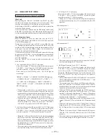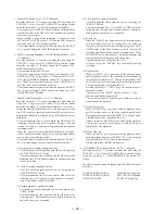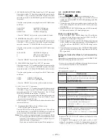
— 16 —
58
US
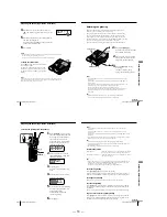
Caller ID Features
2
Continue the operation to call or store the phone number
with the correct number of digits (pages 55 and 56).
Notes
• You need to adjust the number of digits each time you call back from the
Caller ID list as the changes to the Caller ID data is not stored in memory.
• You may not be able to change the number of digits depending on the Caller
ID data.
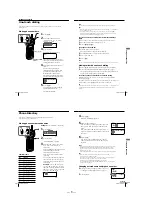
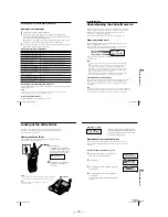
When the local area code matches
SMITH JOHN
201-123-4567
SMITH JOHN
1-123-4567
SMITH JOHN
1-201-123-4567
SMITH JOHN
123-4567
Using the Caller ID list (continued)
59
US
Caller ID Features
Caller ID Features
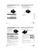
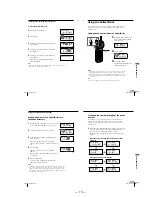
Using “Caller ID with call waiting”
service
This telephone is compatible with the “Caller ID with call waiting”
service. Make sure that your telephone company offers this service.
Like the basic Caller ID service, you need to subscribe to “Caller ID
with call waiting” in order to use this service.
Even though you may have already subscribed to “Caller ID” and
“call waiting” as two separate services, you need to request a
subscription to “Caller ID with call waiting” as a single service.
This is a new service that combines the two services.
Even though you now have a “Caller ID with call waiting”
compatible phone, unless you subscribe to the combined “Caller ID
with call waiting” service, you will not be able to see the name
and number of the second caller.
When a new call comes in while you are talking, the caller’s name
and/or phone number of the new call appears on the display for about
20 seconds.
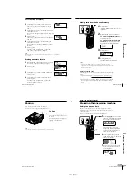
To switch to another caller
1
To switch to the new caller,
press
(CALL WAITING/FLASH)
.
2
To switch back to the first caller,
press
(CALL WAITING/FLASH)
again.
Additional Information
60
US
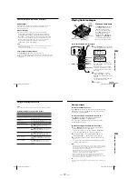
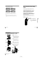
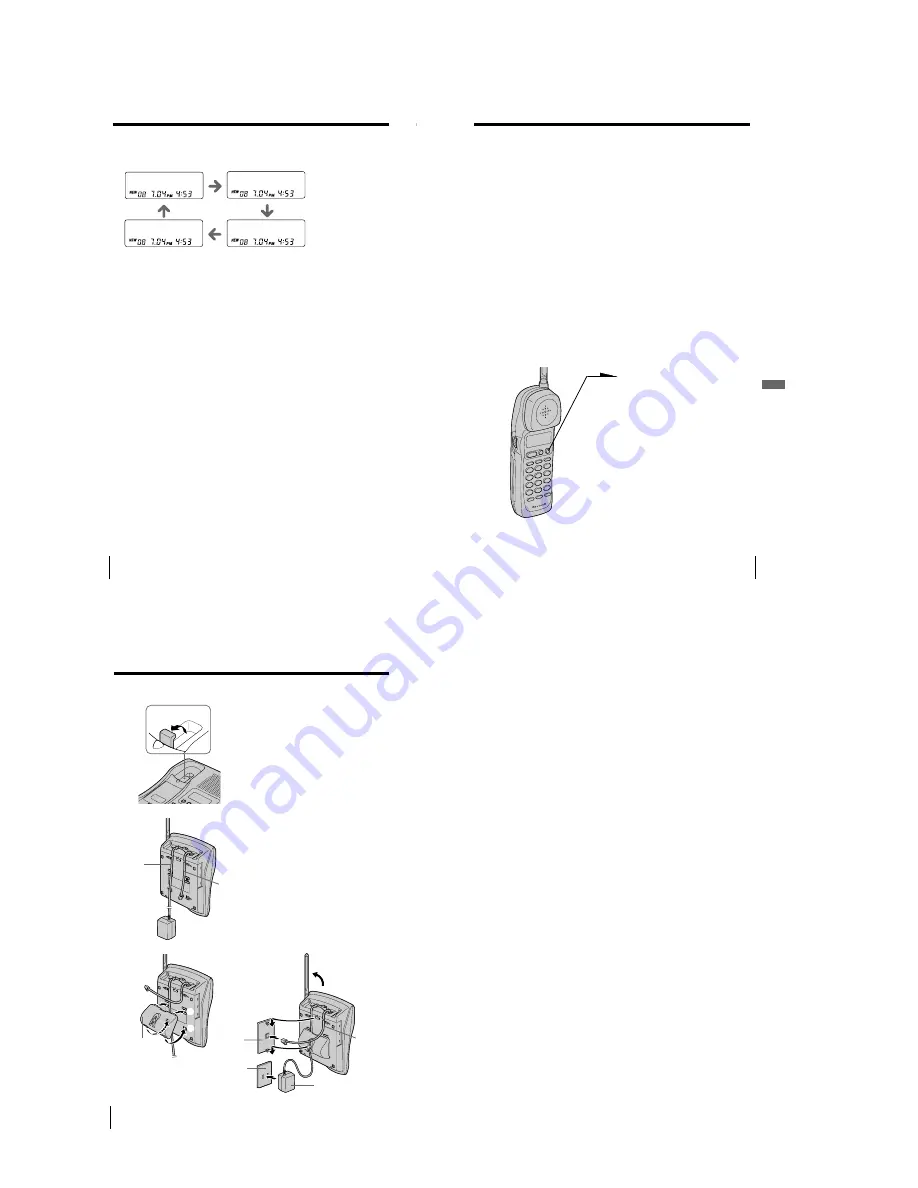
Mounting the base unit on a wall
1
Raise the hang up tab.
2
Plug the telephone line cord to
the LINE jack and the AC power
adaptor to the DC IN 9V jack,
and hook the cords. Use the
shorter cord for mounting.
3
Attach the wall bracket to the
center of the base unit.
Align the
f
marks of the wall
bracket with those of the base
unit.
4
Plug the telephone line cord to
the telephone outlet, and hook
the base unit to the wall plate.
5
Plug the AC power adaptor to
an AC outlet. Then raise the
antenna so that it points
towards the ceiling.
Tip
To remove the wall bracket, press the lower tabs.
1
2
Additional Information
1
2
3
4,5
Telephone
line cord
Wall
bracket
Hang-up tab
Telephone
line cord
AC power
adaptor
AC power
adaptor cord
Wall
plate
AC outlet
Содержание SPP-A9171 - Cordless Telephone With Answering Machine
Страница 38: ...SPP A9171 41 42 6 4 SCHEMATIC DIAGRAM BASE MAIN SECTION 1 2 See page 33 for Note on Schematic Diagrams ...
Страница 39: ...SPP A9171 43 44 6 5 SCHEMATIC DIAGRAM BASE MAIN SECTION 2 2 See page 33 for Note on Schematic Diagrams ...
Страница 41: ...SPP A9171 47 48 6 7 SCHEMATIC DIAGRAM BASE KEY SECTION See page 33 for Note on Schematic Diagrams ...
Страница 43: ...SPP A9171 51 52 6 9 SCHEMATIC DIAGRAM DISPLAY SECTION See page 33 for Note on Schematic Diagrams ...
Страница 45: ...SPP A9171 55 56 6 11 SCHEMATIC DIAGRAM HAND MAIN SECTION See page 33 for Note on Schematic Diagrams ...

