7-13
7.7. Points to note when installing the hoisting system
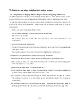
7.7.1. Adjustment of the gap between the pressure receiving ring and the skirt
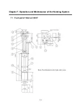
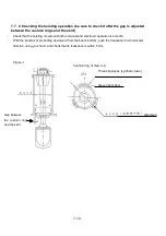
The optimum gap between the pressure receiving ring and the skirt is 2 – 3 mm (refer to Fig. 1). In case
the gap is more than 5 mm, an excessive vibration during the navigation or hoisting failure may occur.
This gap may change depending on the skirt to be manufactured locally or the distortion caused by the
welding of the skirt to the ship’s bottom. Please understand the following points when installing the
hoisting system.
1-1) Points to note when manufacturing the skirt locally
For the material of the skirt, the welding steel for ships must be used.
The skirt must be annealed.
The roundness of the skirt must be within 2 mm at maximum and the inside diameter error must
within 1.5 mm.
1-2) Welding of the skirt to the ship’s bottom
The size of the skirt mounting hole to the ship’s bottom shall be not larger than “the outside diameter
of the skirt + 5 mm”.
The distortion caused by the welding of the skirt to the ship’s bottom shall be ±2 mm.
1-3) Adjustment of the gap between the pressure receiving ring and the skirt
After welding the skirt to the ship’s bottom, the gap must be adjusted in the following manner:
1) After cleaning the flange of the skirt, attach the packing into the bolt hole, place the hoisting system
and temporarily fix it using 3 – 4 bolts.
2) Manually or electrically, lower the hoist to the lower limit.
3) From outside the ship’s bottom, measure the gaps at three locations of the pressure-receiving ring
(portions made of white synthetic resin); they must be 2 – 5 mm.
4) If the gaps are not appropriate, adjust the gap as follows: raise the hoist to the upper limit, remove
the temporary fixing bolts, lift up the hoisting system and insert the spacers into the pressure
receiving ring.
5) Once again, lower the hoist and measure the gaps. If the gaps are appropriate, apply the
packing agent to the flange and packing, and then fix the flange permanently using bolts.
Содержание KCS-3500
Страница 1: ...Model KCS 3500 Color Scanning Sonar Operation Manual Ver 1 6...
Страница 2: ......
Страница 16: ......
Страница 26: ......
Страница 62: ......
Страница 70: ...7 8...
Страница 85: ......
Страница 86: ......
Страница 87: ......
Страница 88: ......
Страница 89: ......
Страница 90: ......
Страница 91: ......
Страница 92: ......
Страница 93: ......
Страница 94: ......
Страница 95: ......
Страница 96: ......
Страница 97: ......
Страница 98: ......
Страница 99: ......
Страница 100: ......
Страница 101: ......
Страница 102: ......

