


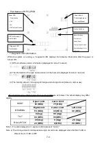


7-12
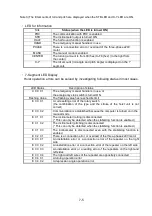
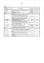
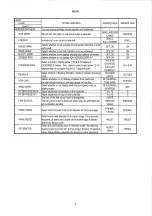
Condition
Check
Actions to be taken /
comment
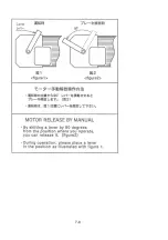
1. Is the brake of the motor functioning properly?
(Is it released?)
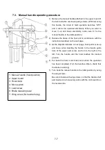
Refer to “manual handle
operating procedure”.
D) The hoist
overruns.
2. Is the upper (or lower) limit switch functioning
properly (is it running idle)?
Adjust the limit switch.
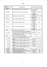
E) The display of the
hoisting rate
changes rapidly
during the operation
1. Is the setting of the rotary switch correct?
1. Is the magnet above the feed screw installed
correctly?
F) The display of the
hoisting rate does
not change.
2. Is the gap between the magnet above the
feed screw and the reed switch too large?
Refer to (3) Adjustment of
the sensor.
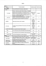
(3) Adjustment of the sensor
The sensor has been adjusted at the factory before shipment, but if it is necessary to make adjustment,
adjust it in the manner shown below.
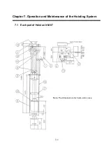
3-1) Ascending and descending limit switches (Type: HL-5000: Upper limit switch and lower limit switch)
(1) Operation
The ascending and descending limit switches control the hoisting motor. When the hoisting pipe
ascends, the upper limit switch is activated and the motor is stopped; similarly, when the hoisting
pipe descends, the lower limit switch is activated and the motor is stopped.
(2) Mounted positions
Two positions at the upper side and lower side of the post
(3) Adjustment procedure
By changing the tap location on the limit switch mounting plate, the positions of the upper limit
switch and the lower limit switch can be moved by 20 mm and 40 mm, respectively (in increments of
20 mm).
3-2) Reed switch for detecting the hoisting rate (Type: GLS-S1)
(1) Operation
Each time the magnet attached to the hoisting feed screw makes one revolution, the reed switch is
turned on/off, and its pulse is measured. Based on the measured pulse, the number of revolutions
is calculated and then the hoisting rate is determined. Since two reed switches are used, the
direction of revolution (in other words, the ascending or descending direction) can be detected.
(2) Mounted positions
The upper rear side of the column
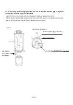
(3) Adjustment procedure
In principle, it is not necessary to make adjustment to the reed switch; however, if necessary, the
distance between the feed screw and the magnet can be adjusted by inserting a washer(s) between
the mounting brackets or the mounting bracket and the column.
Содержание KCS-3500
Страница 1: ...Model KCS 3500 Color Scanning Sonar Operation Manual Ver 1 6...
Страница 2: ......
Страница 16: ......
Страница 26: ......
Страница 62: ......
Страница 70: ...7 8...
Страница 85: ......
Страница 86: ......
Страница 87: ......
Страница 88: ......
Страница 89: ......
Страница 90: ......
Страница 91: ......
Страница 92: ......
Страница 93: ......
Страница 94: ......
Страница 95: ......
Страница 96: ......
Страница 97: ......
Страница 98: ......
Страница 99: ......
Страница 100: ......
Страница 101: ......
Страница 102: ......


