3 Using the PVA-600
3-4
Setting Up the Optional PVA Sensor Kit
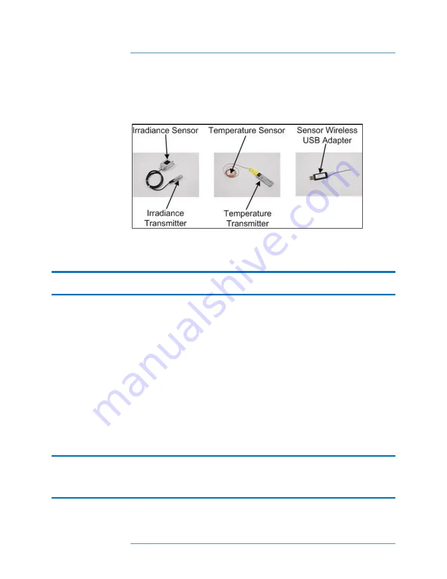
Figure 7 shows the PVA Sensor Kit components that will be set up.
Figure 7. PVA Sensor Kit
1.
Connect the Sensor Wireless USB Adapter to a USB port in your computer.
NOTE
On some PCs, the USB adapters may not fit side-by-side due to their width. If a second
USB position is not available, a USB hub with short connecting cable (<6‖) may be used.
2.
Ensure that the transmitter with the ―I‖ label is connected to the irradiance sensor.
Observe polarity markings.
3.
Ensure that the transmitter with the ―T‖ label is connected to the temperature sensor.
Observe polarity markings.
4.
Position the irradiance sensor in the same plane as the modules under test. For
example, on the surface of a neighboring module that is not in the string of modules
being tested.
5.
Ensure that the irradiance transmitter is not resting on the ground or on the roof, and
is not placed against a metal surface. Elevating the irradiance transmitter improves
the transmission range.
6.
Secure the temperature sensor close to the middle of a PV module. Temperatures
toward the outside of a PV module or array are cooler.
NOTE
The temperature sensor has adhesive tape on it used to secure it to a panel. When the
adhesive tape will no longer hold the temperature sensor to the panel, use duct tape to
hold the sensor tip and at least an inch of wire in intimate contact with the module back
surface.
Содержание PVA-600
Страница 1: ...Solmetric PVA 600 PV Analyzer User s Guide ...
Страница 10: ...x The page left blank intentionally ...
Страница 18: ...1 Introduction 1 8 The page left blank intentionally ...


