background image

Configuration Program

8.0  c

onfiGuration

 p

roGram


 The final step of installation may require custom configuration of your UPS using the enclosed configuration program.  Some configuration 


settings may be changed only while the UPS is off.  These should be set before the UPS is put into full time service powering the critical load.


For most users operating with 120 VAC L-N, the factory default settings will be adequate.  This manual illustrates the features available for 

modification, as well as the factory default setting. 


The factory default L-N setting is 120 VAC. When first powered by the AC input, the UPS will auto sense the utility phase angle between L1 

and L2, setting the UPS to operate as either a 120/208 VAC system (120 degrees, leading or lagging) or a 120/240 VAC system (180 de-

grees).  
 

If your application requires that the L1-N, L2-N voltages be set at 100, 110,115 or 127 VAC, the corresponding phase angle between L1 and 

L2 is restricted.  The VAC settings of 100, 110 and 115 may work only with a phase angle of 180 degrees. A VAC setting of 127 VAC will work 

only with a phase angle of 120 degrees (leading or lagging). 


To confirm the phase angle of the utility input, measure the L1-N, L2-N and L1 L2 VAC of the utility input that is intended for the UPS. If the 

measured L1-L2 voltage is equal to the average L-N voltage times 2.0, then the phase angle is 180 degrees and the L-N VAC maybe set at 

100, 110, 115 or 120 VAC. The nominal L1-L2 voltages for these four settings will be 200, 220, 230 or 240 VAC, respectively. 


If the measured L1-L2 voltage is equal to the average L-N voltage times 1.73, then the phase angle is 120 degrees and the L-N VAC maybe 

set at either 120 or 127 VAC. The nominal L1-L2 voltages for these two settings will be 208 or 220 VAC, respectively. Selecting a L-N nominal 

voltage that is not compatible with the L1-L2 phase angle detected by the UPS when AC input is applied will result in a fault alarm and the 

UPS will not operate from utility power. 


8.1 

S4K6U10000 Configuration Program Features


 The configuration program enables the user to perform the following functions:


1.  Select one of five input/output voltages to match voltages found around the world.


2.  Disable Auto-Restart.


3.  Disable the Line-Neutral-Reversed/Missing-Ground receptacle wiring alarm. (120 VAC single phase models only)


4.  Select frequency converter operation with a fixed output frequency of 50 or 60 Hz.


5.  Enable or disable the audible alarm.


6.  Set the Low Battery Warning alarm time from 2 to 30 minutes.


7.  Enable or disable the Auto-Battery test.


8.  Enable or disable the Auto Restart function.


9.  Set the Auto-Battery test to 7, 14, 21, or 28 days.


10.   Select the number of external battery cabinets connected to the UPS to adjust the remaining runtime calculations reported by the UPS 

software products.


11.   Modify the shutdown setting of DB-9 pin 6 (for information on pin assignments, see 

11.0- Communications

) for models manufactured 

after July 2002.

8.2  What You Will Need


In addition to the S4K6U10000 UPS, you will need the S4K Configuration Program CD and serial cable (beige or tan, three-wire:GND, TX, 

RX; straight through 2-2,3-3,5-5) included  in the UPS accessory box.  A computer desktop or laptop—running Windows 95® or later is also 

required to setup and run the configuration program.

20

Refer to “

S4K Configuration program

” manual (PDF file within 

S4K Configuration CD

) for installing and configuring program.

NOTE

This program is compatible with UPS models beginning with “S4K”, as in “S4K2U1500.” It is not compatible with earlier versions of 

S4000 UPS. 

Содержание S4K6U10000

Страница 1: ...S S4K6U10000 power availability On Line UPS 120 208V 120 240V USER MANUAL...

Страница 2: ......

Страница 3: ...utput Terminal Blocks and Optional Output Distribution 8 5 0 What s Included 9 6 0 Installation and Configuration 10 6 1 Install the Main Cabinet 10 6 1 1 Tower UPS Installation 10 6 1 2 Installing th...

Страница 4: ...ton 21 9 3 L1 L2 Load Level Indicators Two Rows of Indicators 4 Green 1 Amber 22 9 4 Battery Level Indicators 5 Green 22 9 5 Fault Indicator Red 22 9 6 Bypass Indicator Amber 22 9 7 UPS ON Indicator G...

Страница 5: ...own on Battery 25 11 3 UPS Intelligent Communications 25 11 4 Remote Emergency Power Off 26 12 0 Maintenance 27 12 1 Battery Replacement 27 12 1 1 Internal Battery Replacement Procedures 27 12 2 UPS R...

Страница 6: ...lays vertical and horizontal 21 Figure 9 REPO switch connections 26 Figure 10 UPS back panel control location 28 Figure 11 Power module replacement 28 TABLES Table 1 Electrical requirements 15 Table 2...

Страница 7: ...mable liquids gases and corrosive substances This UPS contains no user serviceable parts except the internal battery pack The Off Bypass push button does not electrically isolate internal parts Under...

Страница 8: ...batteries Disconnect charging source prior to connecting or disconnecting battery terminals Determine if the battery is inadvertently grounded If inadvertently grounded remove source of ground Contac...

Страница 9: ...tion Followed By Important Instructions AC Input AC Output Requests The User To Consult The Manual Indicates The Unit Contains A Valve Regulated Lead Acid Battery Recycle DC Voltage Equipment Groundin...

Страница 10: ...ts output voltage whether utility power is present or not It supplies connected equipment with clean sinewave power Sensitive electronic equipment operates best from sinewave power For ease of use the...

Страница 11: ...deal Extracting this sinewave input current achieves two objectives The utility power is used as efficiently as possible by the UPS The amount of distortion reflected on the utility is reduced This re...

Страница 12: ...xternal battery cabinets are available to extend battery run times 3 7 Dynamic Bypass The S4K6U10000 provides an alternate path for utility power to the connected load in the unlikely event of a UPS m...

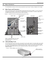
Страница 13: ...three screws at the top of the cover plate and lifting the plate off The two internal battery packs are compact assemblies ready to slide into the battery compartment after the front battery access p...

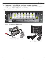
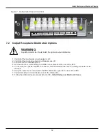
Страница 14: ...venience 8 Figure 3 Hardwire terminal blocks INPUT L1 N L2 N L1 L2 OUTPUT Figure 4 Optional output distribution modules S4KPAD 101 Power Distribution Option with Internal Connector S4KPAD 102 Power Di...

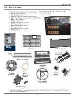
Страница 15: ...Hardware S4K Configuration Program Disk Ferrite Beads 2 MultiLink Serial Cable 10 ft 3m Rack Mount Handles S4K Configuration Program Disk Ferrite Beads 2 Mounting Hardware 9 Front Bezel Vertical Displ...

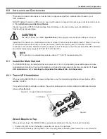
Страница 16: ...tain an ambient temperature range of 32 F to 104 F 0 C to 40 C 6 1 Install the Main Cabinet The S4K6U10000 may be installed either as a tower unit or in a rack depending on available space and use con...

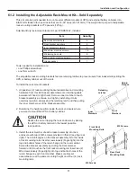
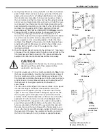
Страница 17: ...e inner member of each bracket assembly as shown in at right by extending it to its outermost position depressing the retaining latch and then pulling the inner member out of the bracket assembly 2 De...

Страница 18: ...ck may be a two person job depending on the weight of the equipment See equipment s user manual 7 Insert the equipment with inner members attached in Step 5 into the bracket assemblies by inserting th...

Страница 19: ...net and maybe installed now Securing hardware and slide rails are sold separately Please contact your local distributor or Sola Hevi Duty representative for these additional options and any assistance...

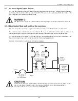
Страница 20: ...d the output circuit breaker on the rear fixed panel of the UPS disconnect all power between the main cabinet and the distribution box The manual bypass switch passes utility power directly to the byp...

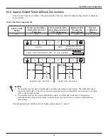
Страница 21: ...it breaker protection according to local codes The utility disconnect should be within sight of the UPS or have an appropriate lock out Maintain service space around the UPS or use flexible conduit 2...

Страница 22: ...e to UPS 3 Snap together the electrical connectors on the UPS and on the output distribution 4 Use the screws removed in Step 2 to attach the output distribution to the rear of the UPS 16 OUTPUT L1 OU...

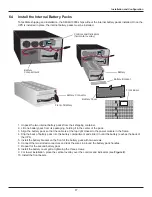
Страница 23: ...the two internal battery packs from their shipping container 2 Lift one battery pack from its packaging holding it in the center of the pack 3 Align the battery pack so that the cable is at the top ri...

Страница 24: ...to apply voltage to the input terminal block see 6 3 1 Distribution Module Electrical Connections 8 Using a voltmeter verify the expected L1 N L2 N and L1 L2 voltages a The bypass lamp by the switch...

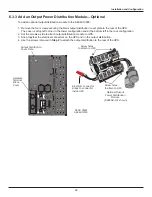
Страница 25: ...access plate from the rear of the UPS 5 Connect the four position Anderson connector of the PAD distribution into the mating connector inside the UPS 6 Using the same four screws attach the PAD distr...

Страница 26: ...120 or 127 VAC The nominal L1 L2 voltages for these two settings will be 208 or 220 VAC respectively Selecting a L N nominal voltage that is not compatible with the L1 L2 phase angle detected by the U...

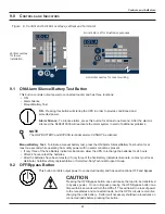
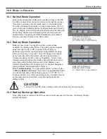
Страница 27: ...nd has dual functions OFF and Bypass Manual Battery Test To initiate a manual battery test press the ON Alarm Silence Battery Test button for at least one second while operating from utility power wit...

Страница 28: ...attery fail this test the red Fault indicator along with the A and C diagnostic indicators will illuminate and an alarm will sound refer to 13 0 Troubleshooting The remote test feature functions with...

Страница 29: ...uns low approximately 2 minutes remaining but this is user configurable The AC Input indicator will extinguish and the Battery indicator will illuminate to warn that a utility problem has occurred Eac...

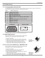
Страница 30: ...ferrite bead groove 3 Position the ferrite bead as close as possible to the end of the cable that connects to the DB 9 connector of the UPS 4 Close the ferrite bead so that the ferrite bead s case sna...

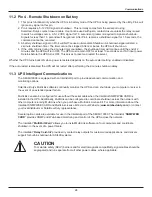
Страница 31: ...ing the 2 minute shutdown delay 11 3 UPS Intelligent Communications The S4K6U10000 is equipped with an Intellislot port to provide advanced communication and monitoring options Sola Hevi Duty s MultiL...

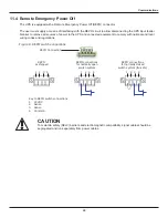
Страница 32: ...comply with national and local wiring codes and regulations Communications CAUTION To maintain safety SELV barriers and electromagnetic compatibility signal cables should be segregated and run separat...

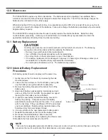
Страница 33: ...port the weight of the battery as it is withdrawn 5 Unpack the new battery assemblies taking care not to destroy the packing Compare new and old battery assemblies to make sure they are the same If so...

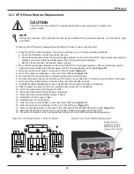
Страница 34: ...ernal batteries are used disconnect the two external battery connectors 9 Slide the power module out the front supporting its weight as it is withdrawn 10 Insert the replacement UPS power module 11 Re...

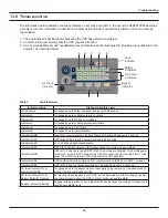
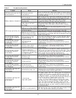
Страница 35: ...every 60 seconds Indicators A D L1 to L2 phase angle unacceptable Indicators B C REPO is currently activated UPS output cannot be started by any method Indicators B D UPS is OFF due to previous REPO...

Страница 36: ...ry 10 seconds more than 2 minutes of run time remaining Low Battery Two short beeps every 5 seconds less than 2 minutes of run time remaining On Bypass Reminder A one second beep every 2 minutes On In...

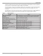
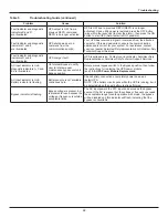
Страница 37: ...due to temperature condition Load is on bypass power Ensure the UPS is not overloaded ventilation openings are not blocked and room ambient temperature is not excessive Wait 30 minutes to allow UPS to...

Страница 38: ...la Hevi Duty Representative or Sola Hevi Duty Technical Support Services AC Input indicator is On diagnostic indicators A C and E are illuminated On Internal Bypass to notify user to rotate manual mai...

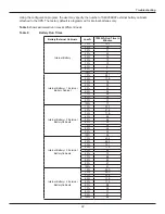
Страница 39: ...Time In Minutes Internal Battery 10 107 20 52 30 31 40 22 50 16 60 13 70 10 80 9 90 7 100 6 Internal Battery 1 External Battery Cabinet 10 251 20 118 30 74 40 52 50 39 60 32 70 26 80 22 90 19 100 17 I...

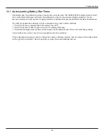
Страница 40: ...will update the anticipated run time calculation only under certain conditions The UPS must have a steady load that is greater than 20 The UPS must be at 100 charge at the start of a battery discharge...

Страница 41: ...00 90 loading 90 VAC 140 VAC 90 70 loading 80 VAC 140 VAC 70 30 loading 70 VAC 140 VAC 30 0 loading 60 VAC 140 VAC L1 N L2 N Operating Voltage Range Without Battery Operation 100 VAC L N Operation 100...

Страница 42: ...A Surge Immunity IEEE ANSI C62 41 Category A B Transportation ISTA Procedure 1A Table 7 UPS Specifications continued Specifications Model Number S4K288INTBAT 2 Required used with S4K6U10000 AND S4K28...

Страница 43: ...m cord L1 N G 4 5 15 20R T type receptacles with 2 20A circuit breaker L2 N G 4 5 15 20R T type receptacles with 2 20A circuit breaker Model Number S4KPAD 102 DIMENSIONS in mm Shipping W x D x H in mm...

Страница 44: ...F 15 C to 50 C Relative Humidity 0 to 95 non condensing Operating Elevation Up to 10 000 ft 3000m at 104 F 40 C without derating Storage Elevation 50 000 ft 15 000m maximum AGENCY Safety UL 1778 c UL...

Страница 45: ...ola Hevi Duty Warranty Information Please see enclosed Terms Conditions and Sales Policies Procedures Software Information Updates for MultiLink software is available for download in the Products sect...

Страница 46: ......

Страница 47: ......

Страница 48: ...or any errors or omissions 2005 Sola Hevi Duty All rights reserved throughout the world Specifications subject to change without notice Sola Hevi Duty name and logo are registered trademarks of EGS El...

Отзывы: