initial Startup and electrical Checks
7.0 i
nitial
S
tartup
and
e
lectrical
c
heckS
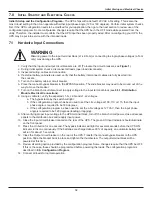
Initial Startup and the Configuration Program
—The UPS ships with a default 120 VAC L-N setting. This is also the
most robust setting in that it can operate with either input phase angle (120 or 180 degrees). Perform initial system checks
first. If the UPS configuration needs to be modified for your application, then go to the next section to review use of the
configuration program. Some configuration changes require that the UPS be in the OFF mode while powered from the
utility. Therefore, the installer must confirm that the UPS input has been properly wired. After re-configuring your UPS, the
UPS may be put into service with the intended loads.
WaRNING
Miswiring power to the input terminal block (L1-L2-N-G) or connecting to single-phase voltages (L-N-G
only) may damage the UPS.
1. Verify that the input and output circuit breakers are off. (To locate the circuit breakers, see
Figure 1
.)
2. During initial system checks, disconnect all loads (open load disconnects).
3. Inspect all wiring, cables and connection.
4. If external battery cabinets are used, verify that the battery interconnect cables are fully inserted into
the sockets.
5. Turn on the battery cabinet circuit breaker.
6. Place the manual bypass breaker in the BYPASS position. The slide bracket may need to be moved out of the
way to move the breaker.
7. Turn on the branch circuit disconnect to apply voltage to the input terminal block (see
6.3.1- Distribution
Module Electrical Connections
).
8. Using a voltmeter, verify the expected L1-N, L2-N and L1-L2 voltages.
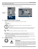
a. The bypass lamp by the switch will light.
b. If the configuration program has been used to set the L-N voltage at 100, 110 or 115, then the input
phase angle is required to be 180 degrees.
c. If the configuration program as been used to set the L-N voltage at 127 VAC, then the input phase
angle is required to be 120 degrees (leading or lagging).
9. After verifying proper input voltage to the UPS terminal block, turn off the branch circuit power, close all access
panels to the distribution box and reapply input power.
10. Close the input circuit breaker located on the rear of the UPS. The green AC Input indicator should illuminate
on the front panel.
11. Press the On button for one second. The bypass indicator will light for several seconds before the UPS ON
indicator turns on continuously. If the batteries are charged above 90% of capacity, an automatic battery test
will run for about 15 seconds.
12. Close the Output circuit breaker on the rear of the UPS. Transfer the manual bypass breaker to the UPS
position. Slide the bracket back in place and tighten the thumbscrew. The output terminal block will be
powered at this time.
13. Review all setting option provided by the configuration program. Some changes require that the UPS be OFF.
If this is the case, these should be programmed before powering the loads. The configuration program is
described in
8.0- Configuration Program
.
14. Connect all loads for normal operation.
18
7.1
hardwire Input Connections
Содержание S4K6U10000
Страница 1: ...S S4K6U10000 power availability On Line UPS 120 208V 120 240V USER MANUAL...
Страница 2: ......
Страница 46: ......
Страница 47: ......

