12.2 UpS power Module Replacement
Maintenance
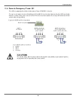
To remove the UPS power module without shutting off power to the connected load:
1. Place the UPS on internal bypass. This may be done by any of the three following methods:
a. Press the Off button on the front panel one time.
b. Slide the bracket away from the manual bypass breaker on the rear of the UPS—this requires loosening the
captive screw and sliding the bracket away from the manual bypass breaker.
c. Remove the front grille covering the power module.
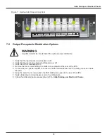
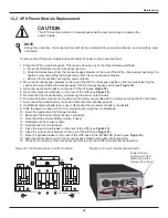
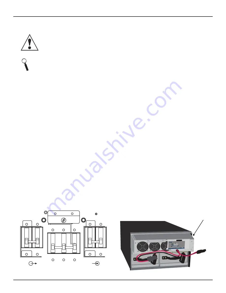
2. Move the manual bypass breaker on the rear of the UPS to the bypass position—this requires loosening the
captive screw and sliding the bracket away from the manual bypass switch (see
Figure 10
).
3. Open the input circuit breaker on the rear of the UPS (see
Figure 10
).
4. Open the output circuit breaker on the rear of the UPS (see
Figure 10
).
5. Remove the front metal bezel by unscrewing the side mounted screws
6. Remove the power module cover grille and the battery cover grille with the screws securing them to the frame.
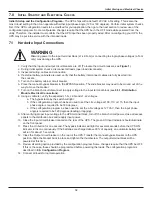
7. Disconnect the slotted battery connectors from the internal battery packs.
8. If additional external batteries are used, disconnect the two external battery connectors.
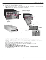
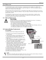
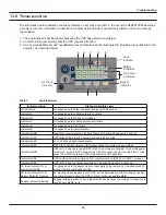
9. Slide the power module out the front, supporting its weight as it is withdrawn.
10. Insert the replacement UPS power module.
11. Reconnect the slotted internal battery connectors.
12. Reconnect the external battery cables, if used.
13. Reattach both front cover grilles.
14. Reattach the front metal bezel.
15. Close the input circuit breaker on the rear of the UPS (see
Figure 10
).
16. Close the output circuit breaker on the rear of the UPS (see
Figure 10
).
17. Move the bypass breaker on the rear of the UPS back to the INVERTER position (see
Figure 10
).
18. Slide the bracket back next to the manual bypass breaker and tighten its thumbscrew.
19. Press the On button on the front panel one time to return the UPS to Normal Mode operation.
NOTE
During the procedure, the connected load will not be protected from power disturbances, such as spikes, sags
and failure.
28
CaUTION
The UPS must be switched to manual bypass before personnel begin to replace the
power module.
Figure 10 UPS back panel—control location
Output Breaker 60A 250V~/T
Input Breaker 60A 250V~/T
Inverter
Bypass
Input
Output
Figure 11 Power module replacement
Power module
pulled out of UPS
(Retaining grilles
removed for clarity)
!
UPStation GXT
!
S4K Industrial UPS
!
- +
AC INPUT BATTERY UPS ON
BYPASS
L1
L2
Содержание S4K6U10000
Страница 1: ...S S4K6U10000 power availability On Line UPS 120 208V 120 240V USER MANUAL...
Страница 2: ......
Страница 46: ......
Страница 47: ......

