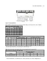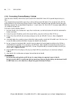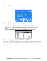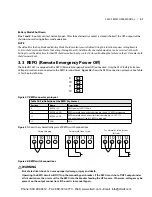
2. Connect the cables to the corresponding terminal of the power input and output terminals�
3. Tighten the screws to 4�52Nm (40 in-lb) with a 13mm (1/2”) torque wrench�
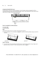
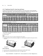
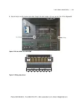
4. Respectively, secure the conduit of the input/output cables through the cable bridges on the rear panel of the UPS
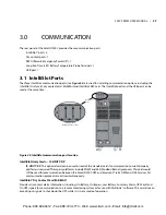
(see
Figure 31
)�
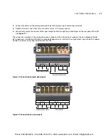
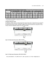
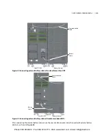
The connection methods in the single-phase input mode and the 3-phase input mode are shown in
Figures 32 and
33
, respectively� Installation of the factory-provided copper bar is essential in the single-phase input mode� The copper
busbar is in the accessory bag included with the UPS�
Figure 32: Connection in single-phase input
Figure 33: Connection in 3-phase input
OUTPUT
INPUT
PE
4
PE
2
1
2
3
1
200/208/220/230/240V
200/208/220/230/240V
OUTPUT
INPUT
PE
4
PE
2
1
2
3
1
200/208/220/230/240V
380/400/415V
S5KC SERIES USER MANUAL | 27
Phone: 800.894.0412 - Fax: 888.723.4773 - Web: www.clrwtr.com - Email: [email protected]

