1.5.2 User Interface Module
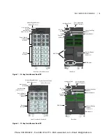
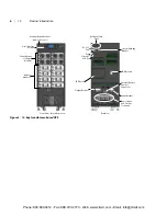
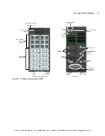
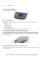
The user interface module is shown in
Figure 7.
Figure 7: User interface module
The user interface module is the primary source of communication between the UPS and the user� The user interface
module permits:
•
Viewing the UPS status
•
Configuring the system
•
Reviewing the event log
•
Silencing the audible alarm
Refer to
4.0 - Operation and Display Panel
for details on operating the user interface module�
1.5.3 System Control Module and System Monitor Module
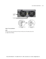
The system control module and the system monitor module are the communication backbone of the UPS� They gather
input from all modules and process the data to control the operation of the system, including monitoring the condition
of each module� Except for the silkscreen, the appearance of the system control module and the system monitor module
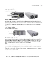
is as shown in
Figure 8.
Figure 8: SolaHD S5KC system control module and the system monitor module
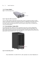
Under normal operation, the green status LED will blink and the yellow fault LED will be Off� For any other condition, refer
to 5�0 - Troubleshooting�
Handle
Green Status LED
Locking Lever
Securing Hole
Yellow Fault LED
12 | 1�0
Product
Introduction
Phone: 800.894.0412 - Fax: 888.723.4773 - Web: www.clrwtr.com - Email: [email protected]

