Sentry 5000-32-IT Controller
Page 8 of 82
2
PRODUCT DESCRIPTION
2.1
Controller Platform
This section describes the Platform for a painted steel wall mount enclosure. Optional Platform designs,
such as rack mount versions contain the same components, but the components may be located in
different positions.
2.1.1 Enclosure and Front Panel
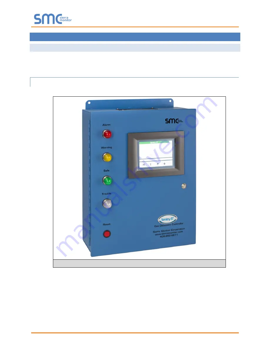
shows the wall mounted enclosure with Front Panel components installed.
The front panel incorporates status indicators for Alarm (red), Warning (amber), Safe (green) and Trouble
(blue), a Touch Panel Computer (TPC) graphical interface screen, a Reset Button and a Door Lock.
Figure 1:
Controller
/Platform External View
Содержание Sentry 5000-32-IT
Страница 28: ...Sentry 5000 32 IT Controller Page 28 of 82 Figure 15 Analog Input Wiring ...
Страница 29: ...Sentry 5000 32 IT Controller Page 29 of 82 Figure 16 PSG Sentry Classic Wiring ...
Страница 30: ...Sentry 5000 32 IT Controller Page 30 of 82 Figure 17 Modbus Wiring ...
Страница 31: ...Sentry 5000 32 IT Controller Page 31 of 82 Figure 18 Top Board Relay Digital Output Wiring ...
Страница 32: ...Sentry 5000 32 IT Controller Page 32 of 82 Figure 19 Analog Output Wiring ...
Страница 33: ...Sentry 5000 32 IT Controller Page 33 of 82 Figure 20 Digital Input Wiring ...
Страница 34: ...Sentry 5000 32 IT Controller Page 34 of 82 Figure 21 Bottom Board Relay Wiring ...


