Sentry 5000-32-IT Controller
Page 23 of 82
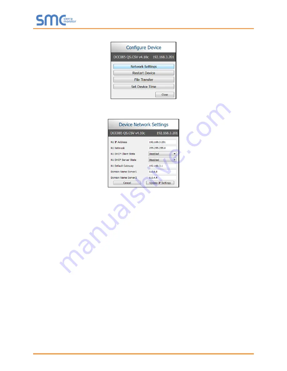
5. Select Network Settings in the Configure Device window.
6. Modify the IP Address (N1 IP Address field) of the ProtoNode Ethernet port.
Change additional fields as needed.
NOTE: If the ProtoNode is connected to a router, the Default Gateway field of the ProtoNode
should be set to the IP Address of the connected router.
NOTE: Do not change the DHCP Server State (N1 DHCP Server State field).
NOTE:
If DNS settings are unknown, set DNS1 to “8.8.8.8” and DNS2 to “8.8.4.4”.
7. Click Update IP Settings, then click on
the “Change and restart” button to reboot the ProtoNode
and activate the new IP Address.
8. Finally, go back to the to FieldServer Toolbox device list and click the Connect button of the
ProtoNode to access the Sentry InSite Appliance GUI. See
Section
Содержание Sentry 5000-32-IT
Страница 28: ...Sentry 5000 32 IT Controller Page 28 of 82 Figure 15 Analog Input Wiring ...
Страница 29: ...Sentry 5000 32 IT Controller Page 29 of 82 Figure 16 PSG Sentry Classic Wiring ...
Страница 30: ...Sentry 5000 32 IT Controller Page 30 of 82 Figure 17 Modbus Wiring ...
Страница 31: ...Sentry 5000 32 IT Controller Page 31 of 82 Figure 18 Top Board Relay Digital Output Wiring ...
Страница 32: ...Sentry 5000 32 IT Controller Page 32 of 82 Figure 19 Analog Output Wiring ...
Страница 33: ...Sentry 5000 32 IT Controller Page 33 of 82 Figure 20 Digital Input Wiring ...
Страница 34: ...Sentry 5000 32 IT Controller Page 34 of 82 Figure 21 Bottom Board Relay Wiring ...


