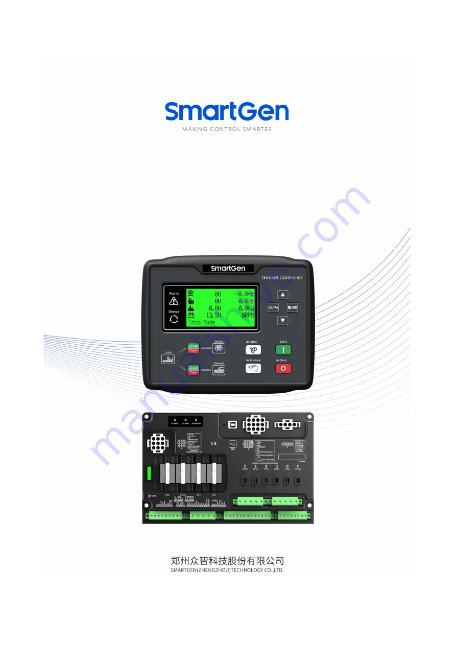
HGMS62
SPLIT TYPE GENSET CONTROLLER
USER MANUAL
HGMS62D Display Module
HGMS62M Master Control Module
Страница 1: ...HGMS62 SPLIT TYPE GENSET CONTROLLER USER MANUAL HGMS62D Display Module HGMS62M Master Control Module...
Страница 2: ...ncluding photocopying or storing in any medium by electronic means or other without the written permission of the copyright holder Applications for the copyright holder s written permission to reprodu...
Страница 3: ...hlights an essential element of a procedure to ensure correctness CAUTION Indicates a procedure or practice which if not strictly observed could result in damage or destruction of equipment WARNING In...
Страница 4: ...OWN ALARMS 17 6 3 TRIP AND STOP ALARMS 18 6 4 TRIP ALARMS 19 7 CONNECTIONS 20 7 1 HGMS62M CONTROLLER PANEL 20 7 2 HGMS62D CONTROLLER REAR PANEL 23 7 3 HGMS62 WIRE HARNESS DESCRIPTION 24 8 PARAMETER RA...
Страница 5: ...52 14 1 CUMMINS ISB ISBE 52 14 2 CUMMINS QSL9 52 14 3 CUMMINS QSM11 IMPORT 52 14 4 CUMMINS QSX15 CM570 53 14 5 CUMMINS GCS MODBUS 53 14 6 CUMMINS QSM11 53 14 7 CUMMINS QSZ13 54 14 8 DETROIT DIESEL DD...
Страница 6: ...GMS62CAN HGMS62D HGMS62MCAN HGMS62D Display control module HGMS62M MPU interface suitable for ESC controlled engines HGMS62MCAN CAN BUS interface suitable for ECU controlled J1939 engines Different ha...
Страница 7: ...can be set from the front panel all parameters can be adjusted via USB interface or RS485 interface of PC A variety of temperature pressure and fuel level sensor curves can be used directly and can b...
Страница 8: ...curacy 0 1Hz AC Current Rated 5A Range 0A 10A Resolution 0 1A Accuracy 1 Speed Sensor Voltage Range 1V 24V RMS Frequency Range 5Hz 10000Hz Charger D Voltage Range DC0V DC60V continuous power supply Re...
Страница 9: ...167 45mm HGMS62M 243 158 65mm Panel Cutout HGMS62D 186 141mm HGMS62M hole space 230 5 125 5mm aperture 5 5 CT Secondary Current Rated 5A Working Temperature 25 70 C Working Humidity 20 93 Storage Temp...
Страница 10: ...nual Press this key to set the module as Manual mode Auto Press this key to set the module as Auto mode C O Can control breaker close open in Manual mode Set Confirm Press this key to enter menu inter...
Страница 11: ...Fast flashing 5 times per second NOTE1 Status indicator always illuminates before ETS and after crank success distinguishes during other periods NOTE2 Gen normal indicator always illuminates in norma...
Страница 12: ...his period alarms of low oil pressure high water temperature under speed failed to charge are disabled As soon as this delay is over genset will enter into Start Idle Delay if configured g During star...
Страница 13: ...nually to control load close open b Manual Stop pressing can shut down the running genset detailed procedures please refer to No b f of Auto Stop Sequence 4 5 EMERGENCY START In manual mode pressing a...
Страница 14: ...Disable If open detection is enabled gen on load is transferred to gen off load after open delay transfer failure detection begins when open outputs when detection time is due if open failure then wai...
Страница 15: ...l send warning alarm signal 9 Stop Failure When Fail to stop delay is over if engine not stop completely controller will send warning alarm signal 10 Charge Failure When genset charger voltage is lowe...
Страница 16: ...gnal 25 Level Sensor Open When level sensor is open and open action selects Warning controller will send warning alarm signal 26 Low Level When level value is lower than threshold controller will send...
Страница 17: ...threshold controller will send shutdown alarm signal 9 Fail to Start Within set start times if fails to start controller will send shutdown alarm signal 10 Gen Over Current When genset current is high...
Страница 18: ...oller will send shutdown alarm signal 26 Input Shutdown When digital input is active for shutdown alarm controller will send shutdown alarm signal 6 3 TRIP AND STOP ALARMS When controller detects trip...
Страница 19: ...overcurrent action selects Trip controller will send trip alarm signal 2 Reverse Power When genset reverse power value power is negative is higher than threshold and reverse power action selects Trip...
Страница 20: ...inal after passing the fuse 4 Fuel Relay 1 5mm2 B is supplied by 2 points rated 10A Relay specification DC 24V pluggable 5 Crank Relay 1 5mm2 6 Charger D 1 0mm2 Connect charger D WL terminal if charge...
Страница 21: ...MP1 0 5mm2 HGMS62MCAN this terminal connects ECU CANBUS interface 120 shielding line recommended to use its single end should be grounded HGMS62M connects speed sensor shielding line is recommended t...
Страница 22: ...or controller 45 Genset N2 Line Input 1 0mm2 Connect N line of genset output Connector A Connect to HGMS62D 1 B IN 1 5mm2 Connect terminal 6 B OUT to this terminal through a power switch to supply for...
Страница 23: ...is connected with main terminal 40 Connect to terminal N of charger 2 Mains R Phase Input 1 0mm2 This terminal inside is connected with main terminal 37 Connect to terminal L of charger 3 Charger Outp...
Страница 24: ...ower 7 3 HGMS62 WIRE HARNESS DESCRIPTION Table 12 HGMS62 Wire Harness Description Harness Port Harness Length Diagram No Function Cable Size XS HGMS62DM XS HGMS62DM S 1 MAINS N 1 0mm2 0 55m 1 05m 2 MA...
Страница 25: ...nable 30 30000 100 Primary 30 1000 100 Secondary 8 Over Voltage Setting 0 1 1 0 Disable 1 Enable 0 200 120 Set value mains rated voltage PCT 0 200 116 Return value mains rated voltage PCT 0 3600 s 5 C...
Страница 26: ...osing after genset entering high speed running 9 Cooling Time 0 3600 s 10 Cooling time before stopping after genset off load 10 Stop Idle Time 0 3600 s 0 Genset idle running time when stopping 11 ETS...
Страница 27: ...e engine rated speed PCT 0 3600 s 2 Confirm time for over speed shutdown detection 9 Under Speed Shutdown 0 1 1 0 Disable 1 Enable 0 200 80 Set value engine rated speed PCT 0 3600 s 3 Confirm time for...
Страница 28: ...d engine disconnect which can be used separately or together aiming at disconnecting starting motor and engine as soon as possible 18 Crank Disconnect Frequency 0 200 24 Set value is percentage of gen...
Страница 29: ...nsor 3 Rated Voltage 30 30000 V 230 Provide standard for gen over under loading voltage If PT is used it is PT secondary voltage 4 Loading Voltage 0 200 85 Set value is gen rated voltage percentage co...
Страница 30: ...0 Disable 1 Enable 0 200 84 Set value gen rated voltage PCT 0 200 86 Return value gen rated voltage PCT 0 3600 s 5 Confirm time for gen under voltage warning detection 14 Gen Over Freq Warning 0 1 1...
Страница 31: ...ip 8 Over Power Set 0 1 0 0 Disable 1 Enable 0 200 110 Set value load rated power percentage 0 200 105 Return value load rated power percentage 0 3600 s 5 Confirm time for over power detection 9 Over...
Страница 32: ...ensor Setting Temperature Sensor 1 Curve Type 0 15 8 SGD See Table 16 2 Open Action 0 2 0 0 Warning 1 Shutdown 2 None 3 Over High Shutdown 0 1 1 0 Disable 1 Enable 50 300 C 98 When external temperatur...
Страница 33: ...5 Return value when external temperature value is less than or equal to it coolant heating will stop 0 3600 min 60 Coolant heating control output time Oil Pressure Sensor 1 Curve Type 0 15 8 SGD See T...
Страница 34: ...it low level shutdown will be issued This value is always judged 0 3600 s 5 Confirm time for low level shutdown detection 5 Fuel Pump Output 0 1 0 0 Disable 1 Enable 0 300 10 When external level valu...
Страница 35: ...hen the input port is active it is the LCD display content Input Port 5 Setting Same as setting of input port 4 Input Port 6 Setting Input Port 7 Setting Input Port 8 Setting Input Port 9 Setting Rela...
Страница 36: ...nation Output 6 13 Reserved 14 Reserved 15 Reserved 16 Reserved 17 Air Flap Control Action in over speed shutdown and emergency shutdown it can close engine inlet port 18 Audible Alarm Action in warni...
Страница 37: ...U Stop Suitable for engine supports ECU used for control ECU stop 41 ECU Power Suitable for engine supports ECU used for control ECU power 42 Pulse Raise Speed Output Action after entering high speed...
Страница 38: ...m occurs 80 Input Port 3 Shutdown Action when input port 3 shutdown alarm occurs 81 Input Port 4 Shutdown Action when input port 4 shutdown alarm occurs 82 Input Port 5 Shutdown Action when input port...
Страница 39: ...when mains under voltage warning occurs 130 Mains Phase Seq Error Action in mains sequence is wrong 131 Mains Loss of Phase Action in mains phase lose 132 138 Reserved 139 High Temp Warn Action when h...
Страница 40: ...ts freely can set the delayed time and output time after entering into period Condition output S2 can be set as any contents in output ports NOTE1 When delay time and output time both are 0 in period...
Страница 41: ...ut port 3 is active or not customc combination output is not outputting 8 3 DEFINED CONTENTS OF DIGITAL INPUT 1 9 Table 15 Defined Contents of Digital Input 1 9 All GND B Active No Type Function Descr...
Страница 42: ...ts are inhibited in this mode 23 Box Temp High Warning When input is active it means box temperature high warning alarm is issued 24 Reset Maintenance Time When input is active controller will reset m...
Страница 43: ...a input ports 48 Alternative Config 2 Active 49 Alternative Config 3 Active 50 Reserved 8 4 SENSOR SELECTION Table 16 Sensor Selection No Items Content Description 1 Temperature Sensor 0 Not used 1 Us...
Страница 44: ...e Speed 6 Oil pressure Speed Frequency NOTE a There are 3 kinds of crank disconnect conditions Speed frequency and oil pressure can be used alone Oil pressure is used with speed and generator frequenc...
Страница 45: ...er than under voltage threshold otherwise over voltage and under voltage will occur at the same time c The over speed threshold must be greater than under speed threshold otherwise over speed and unde...
Страница 46: ...f there is difference between standard sensor curve and chosen sensor curve select Defined Sensor and then input defined sensor curve When sensor curve is inputted X value resistance must be in accord...
Страница 47: ...of preventing engine to disconnect crank e g Connect wire of fuel value press start button again genset will start If everything goes well genset will normally run after idle running if configured Dur...
Страница 48: ...HGMS62 Split Type Genset Controller User Manual Page 48 of 58 12 TYPICAL APPLICATION Fig 5 HGMS62 Typical Application Diagram Fig 6 HGMS62CAN Typical Application Diagram...
Страница 49: ...HGMS62 Split Type Genset Controller User Manual Page 49 of 58 Fig 7 Single Phase 2 Wire Diagram Fig 8 2 Phase 3 Wire Diagram...
Страница 50: ...backwards towards the back of the module ensuring four clips are inside their allotted slots Turn the fixing clip screws clockwise until they make contact with the panel NOTE 0 27N m 2 75kgf cm torqu...
Страница 51: ...nd the other end vacant The other two signal lines are respectively connected to terminal 26 and terminal 27 At full speed output voltage range is 1 24 VAC RMS 12VAC is recommended rated speed During...
Страница 52: ...relay output 39 Crank relay output Connect to starter coil directly Table 22 9 Pins Connector Terminals of controller 9 pins connector Remark CAN H SAE J1939 signal C Using impedance 120 connecting li...
Страница 53: ...nformation of engine Engine types are QSX15 QST30 QSK23 45 60 78 and so on Table 27 D SUB Connector 06 Terminals of controller D SUB connector 06 Remark Fuel relay output 5 8 Outside expand relay when...
Страница 54: ...to starter coil directly CAN H CAN H Using impedance 120 connecting line CAN L CAN L Using impedance 120 connecting line Engine type Common J1939 14 9 DEUTZ EMR2 Table 32 F Connector Terminals of cont...
Страница 55: ...engine with ADEC ECU7 and SAM module Table 36 ADEC X1 Port Terminals of controller ADEC X1 port Remark Fuel relay output X1 43 X1 Terminal 28 connected to battery negative Crank relay output X1 37 X1...
Страница 56: ...H Crank relay output E Aux output 2 P Set aux output 2 as ECU Power Table 41 Data bus Connector Terminals of controller Data bus connector Remark CAN H 1 Using impedance 120 connecting line CAN L 2 U...
Страница 57: ...s Port Terminals of controller Engine 42 pins port Remark Fuel relay output 1 40 Connect to engine ignition switch Crank relay output Connect to starter coil directly CAN H 1 35 Using impedance 120 co...
Страница 58: ...sor and connections High Temp Alarm After Crank Disconnect Check temperature sensor and connections Shutdown Alarm During Running Check switch and connections according to information on LCD Check aux...