


3. The inlay cannot be fitted on some handles, such as offset handles,
when they are already installed. Push the inlay onto the outer handle
with the logo facing outwards in such cases. You can do this with most
handles.
4. Optional: In a lock with an 8.5 mm or 10 mm spindle, push the corres-
ponding sleeve (8 mm --> 8.5 mm [not included in the supply package]
or 8 mm --> 10 mm) through the retainer opening in the mortise lock
from the inside.
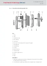
5. Push the inside fitting (8) spindle through the retainer slot in the door's
mortise lock (6), so that the fitting is flush with the door. Ensure that
you do not squash the 3-pole cable when doing so.
6. Position the inside fitting (8) in such a way that it is parallel to the door.
7. Mark the drill holes required on the door through the corresponding
holes in the inside fitting (8).
8. Remove inside fitting (8) from the door.
9. Drill the holes with a diameter of 8 mm (top hole) and 13 mm (lower
hole) through the door.
10. Push inlay (1) onto the outer handle (3). Depending on the handle
model, it may not be possible to fit it once the handle is installed.
11. Insert outer handle (3) horizontally into the outer fitting (4), placing it in
the direction that you require, depending on whether it is a DIN left-hand
or right-hand door.
12. Place handle fastener piece (5) into position (see Figures 2 and 3).
13. Hold the outside handle (3) and use the spanner to rotate the fastener
piece (5) about 75° to the right until it fits into position (Figures 4 and
5). If you do not fit it correctly, the handle may come loose again.
14. The inside fitting (8) is mounted onto the inner surface of the door. Push
the spindle for the inside fitting (8) through the retainer slot in the mor-
tise lock (6) and push the inside fitting (8) onto the door until it is about
5 cm away.
15. Push the 3-pole cable for the inside fitting through the lower hole (13
mm in diameter) and ensure that it doesn't get caught or buckled.
16. Push inside fitting (8) through the door completely, so that it is flush
with the door. In doing so, place the cable escutcheon into the lower drill
hole.
17. The outer fitting is mounted from the outer side of the door.
18. Insert the lower spacing bolt (7) into the outer fitting; the upper spacing
bolt (7) is pre-fastened into position in the factory.
19. Push the outer fitting retainer slot onto the spindle while pushing the
two spacing bolts (7) through the drill holes up to a gap of 2 cm.
SmartHandle
SmartIntego
(Manual)
8. Installation (manual)
64 / 160
Содержание SI:SmartHandle Series
Страница 1: ...SmartHandle SmartIntego Manual 28 10 2020...
Страница 25: ...6 5 Distances and door thicknesses SmartHandle SmartIntego Manual 6 Designs 25 160...
Страница 131: ...SmartHandle SmartIntego Manual 8 Installation manual 131 160...
Страница 132: ...9 Outer fitting is mounted SmartHandle SmartIntego Manual 8 Installation manual 132 160...
Страница 136: ...2 Remove the uppermost battery SmartHandle SmartIntego Manual 8 Installation manual 136 160...
Страница 137: ...3 Screw on the inside fitting SmartHandle SmartIntego Manual 8 Installation manual 137 160...
Страница 141: ...3 Press the inside of the cover firmly SmartHandle SmartIntego Manual 8 Installation manual 141 160...
Страница 145: ...10 Configuration See TechGuide WO SVCN SmartHandle SmartIntego Manual 10 Configuration 145 160...
Страница 146: ...11 Status messages See TechGuide WO SVCN SmartHandle SmartIntego Manual 11 Status messages 146 160...
Страница 147: ...12 Signal See TechGuide WO SVCN SmartHandle SmartIntego Manual 12 Signal 147 160...