


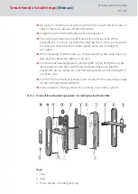


16. Inlay
17. Inlay
Installation:
1. Optional: handles, escutcheons, fittings and other door furniture fitted
to the door are to be removed.
2. The SI:SmartHandle is partly assembled when supplied; see Disas-
sembly.
3. The inlay cannot be fitted on some handles, such as offset handles,
when they are already installed. Push the inlay onto the handle with the
logo facing outwards before installing the handle. You can do this with
most handles.
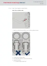
4. Push inlay (1) onto the outer handle (3). Depending on the handle
model, it may not be possible to fit it once the handle is installed.
5. Insert outer handle (3) horizontally into the outer fitting (4), placing it in
the direction that you require, depending on whether it is a DIN left-hand
or right-hand door.
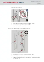
6. Place handle fastener piece (5) into position (see Figures 2 and 3).
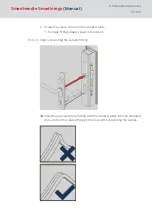
7. Hold the outside handle (4) and use the spanner to rotate the handle
fastener piece (5) about 75° to the right until it fits into position (Figures
4 and 5). If you do not fit it correctly, the handle may come loose again.
8. First, you must adjust the four supplied mounting screws (10) to the
door thickness using the following formula. The screws (10) have also
been treated with thread-locking fluid to prevent the handle coming
loose due to vibrations, for example. Important: this fluid hardens within
24 hours of the screws being fastened for the first time. If the screws are
undone again, the fluid no longer secures the screws.
NOTE
Required screw length = door thi 4 mm. The tolerance is ± 1 mm.
9. The outer fitting (4) is mounted from the outer side of the door. Push
the cable from the outer fitting (4) through the small, upper hole in the
adapter plate (6).
10. Place the adapter plate (6) on the inside surface of the outer fitting (4),
so that it is flush with the fitting.
11. Use the three screws (7) to fasten the adapter plate (6) to the outer fit-
ting and then tighten firmly by hand (about 5-7 Nm).
12. Push the cable from the outer fitting through one of the two upper holes
in the mortise lock (8).
SmartHandle
SmartIntego
(Manual)
8. Installation (manual)
100 / 160
Содержание SI:SmartHandle Series
Страница 1: ...SmartHandle SmartIntego Manual 28 10 2020...
Страница 25: ...6 5 Distances and door thicknesses SmartHandle SmartIntego Manual 6 Designs 25 160...
Страница 131: ...SmartHandle SmartIntego Manual 8 Installation manual 131 160...
Страница 132: ...9 Outer fitting is mounted SmartHandle SmartIntego Manual 8 Installation manual 132 160...
Страница 136: ...2 Remove the uppermost battery SmartHandle SmartIntego Manual 8 Installation manual 136 160...
Страница 137: ...3 Screw on the inside fitting SmartHandle SmartIntego Manual 8 Installation manual 137 160...
Страница 141: ...3 Press the inside of the cover firmly SmartHandle SmartIntego Manual 8 Installation manual 141 160...
Страница 145: ...10 Configuration See TechGuide WO SVCN SmartHandle SmartIntego Manual 10 Configuration 145 160...
Страница 146: ...11 Status messages See TechGuide WO SVCN SmartHandle SmartIntego Manual 11 Status messages 146 160...
Страница 147: ...12 Signal See TechGuide WO SVCN SmartHandle SmartIntego Manual 12 Signal 147 160...