background image


38 


10.2 

Tool integrity assessment (teeth) 


Before leaving the operator’s seat on the prime mover, make sure the area is flat, the 
prime mover is stabilised, the machine is resting on the ground, and the keys have been 
removed from the ignition. 

 
Every tooth is subject to constant wear due to contact with the material cut. The greater the wear, the lesser 
the tooth’s capacity for breaking into the material. 
What is more, as tooth wear increases, the work progress slows. This means that, if you use very worn teeth, 
the machine’s productivity drops noticeably. 
Replacing the teeth promptly will ensure the machine is always used to its full potential. 
It is always worthwhile checking for signs of wear as the tooth only really performs well throughout its working 
life if it is worn down in the best possible way. 
 

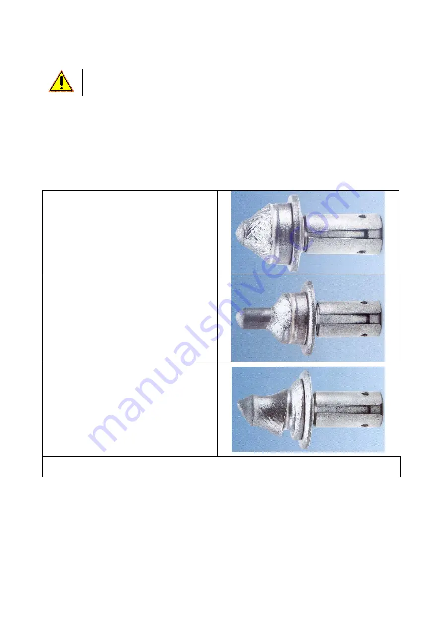
TOOTH WEAR 


A: Features of an ideally worn tooth


The remaining part of the carbide tip is 
symmetrically shaped  
The body has a uniform, tapered shape,  
The body has enough bulk to support the carbide 
core. 
Tooth is worn and needs replacing. 


B:


Tooth that has worked on soft materials 

If a tooth has been used on an overly soft 
material, the body will wear quicker than the tip, 
and the tip will end up snapping off.  Additionally, 
the altered tooth shape will increase tooth holder 
wear. 
Tooth is worn and needs replacing. 


C: Tooth which has not rotated properly


The teeth which are subject to uneven use, wear 
out fast.  Wear of this kind is usually due to the 
tooth not turning round in its holder. The wear may 
be due to a worn tooth holder or the presence of 
small particles of planed material between the 
shank of the tooth and the seat in which it is fitted.


In this instance, clean the seat and lubricate with 
diesel fuel. 
Tooth is worn and needs replacing.


N.B.

 the tooth shown in the picture is a standard model. but the concepts apply to all teeth models. 


Содержание PL 4520

Страница 1: ...6810628 www simex it simex simex it No part of this manual may be reproduced or translated without prior written permission from its owner The information and illustrations contained in this manual ar...

Страница 2: ...ith 5 line hydraulic system to the prime mover 23 9 6 Hydraulic disconnection of the standard machine with 3 or 5 line hydraulic system from the prime mover 24 9 7 Disconnecting the machine from the p...

Страница 3: ...4 12 Recommissioning 44 13 Spare parts and accessories 44 14 Disposal 44 15 Troubleshooting 45 16 Optionals 47 16 1 Special drums 47 16 2 Removable skid 48 16 3 Misting unit 49 16 4 Hydraulic tilt adj...

Страница 4: ...urer in Italian In order to meet certain legal or business requirements the original information is translated into the other official languages The contents of this manual may be altered without prio...

Страница 5: ...2 Declaration of conformity The declaration of conformity is filled in and signed by SIMEX S r l s legal representative and attached to this manual Following an example of the declaration of conformit...

Страница 6: ...rained staff member who is authorised to install operate adjust clean and transport the machine MAINTENANCE ENGINEER This is the person s trained and authorised to work on the machine for routine main...

Страница 7: ...4 Warning RISK OF CRUSHING STICKER DO NOT ACCESS THE AREA OF RISK Code 20937 Warning NO WORK MAY BE CARRIED OUT ON THE MACHINE UNTIL DRUM ROTATION HAS STOPPED Code 20942 Warning READ THE MANUAL CAREFU...

Страница 8: ...d transfers stickers are always in place and legible If this is not the case affix or replace them obtaining the materials required from the manufacturer 4 stickers HOOK UP POINT FOR LIFTING PURPOSES...

Страница 9: ...impair operation or cause injury to the operator Before using the machine make sure all the safety devices are correctly in place and in good condition if any broken devices are found replace them im...

Страница 10: ...e tilted transversally either automatically on the standard machine or using a hydraulic cylinder optional If planing is required up to and beyond the external edge of the prime mover a side shift ope...

Страница 11: ...PL A B B1 C D E 4520 1680 1180 1270 900 450 610 5020 1680 1250 1350 950 500 665 5520 1680 1180 1270 900 550 710 6020 1680 1250 1350 950 600 765 7520 1680 1300 1400 960 750 910 Version with water tank...

Страница 12: ...he correct weight which is different to the one stated in the table will be specified on the CE data plate Example of how to calculate the hydraulic motor power Q l min x P bar A HP 1 36 A kW 450 Key...

Страница 13: ...tion cover 7 Side shift 8 Side shift hydraulic cylinder 9 Transversal tilt signal light 10 Right hand side plate 11 Left hand side plate 12 Spring jack 13 Valve for electro hydraulic controls on machi...

Страница 14: ...14...

Страница 15: ...ntal conditions the working are has to be illuminated min 200 lux either by the prime mover or by working area fir o mobile lights SIMEX S r l cannot be held responsible for any mishandling of the mac...

Страница 16: ...Before touch the working tools teeth wait until they cool down and suitable protection gloves MUST be used 1 Guard for the motor hoses only featured on the version with 3 hydraulic lines pressure retu...

Страница 17: ...the event of damage give notice of the fact to the carrier in writing within 8 days of receipt of the machine If upon delivery major damage caused during transportation is noted or any parts that shou...

Страница 18: ...let and handle it with a fork lift truck or a transpallet Handling over long stretches Secure the machine to a pallet using a fork lift truck or a transpallet for handling then load it onto the means...

Страница 19: ...plied to skid loaders where the driver s seat is accessed from the front of the p m GETTING ON on the right hand side of the machine A place your left foot on the lower step on the self levelling plan...

Страница 20: ...t compact ground in the non operative position and away from ditches stores of fuel or any other substances and electrical substations fig 1 opposite 1 2 Move the prime mover towards the machine slowl...

Страница 21: ...o levers figures 4 and 5 opposite to engage the quick coupling lock pins Check that the levers are locked in the retaining position and that the pins are fitted properly inside the slots on the machin...

Страница 22: ...for signs of leaks near the hosing fittings Fig 3 Fig 4 The two figures show examples of hose connections fig 3 and the power cable connection fig 4 to the prime mover The machine is connected to the...

Страница 23: ...f the engine remove the ignition keys and get off the prime mover now check for signs of leaks near the hose fittings Fig 5 The figure shows an example of how to connect the hoses to the prime mover T...

Страница 24: ...of the standard machine with 3 or 5 line hydraulic system from the prime mover Before leaving the operator s seat on the prime mover make sure the machine is resting on flat ground the prime mover is...

Страница 25: ...el stores electrical substations or any other hazard risk fig 1 para 9 3 Once you have turned off the diesel engine removed the ignition key and stabilised the prime mover with the parking brake stabi...

Страница 26: ...ts 1 Release the depth adjustment lock Release the depth adjustment lock as shown in fig 1 fig 1 2 Insert the crank supplied and turn it to adjust the planing depth as show in fig 2 To quantify the pl...

Страница 27: ...fully 2 Make sure the side plates are resting on the ground and that the ground is flat and compact 3 Change the depth setting see para 9 8 using both screws until the drum is skimming the ground Tur...

Страница 28: ...rkplace To remove the drum proceed as follows Set the planing depth at zero see para 9 8 fig A Undo the screws fastening the guide pins and the front guide using appropriate tools fig A and remove the...

Страница 29: ...8 and the two slots fig 9 the cutting part of the machine adapts perfectly to the ground requiring planing and maintains a constant grip on it Additionally it is not affected by the different angles...

Страница 30: ...following checks must always be performed prior to starting the machine check that there are no leaks in the hydraulic circuit check that the mechanical and electrical connection has been made correct...

Страница 31: ...the machine unattended without first engaging the safety locks and removing the ignition keys Cordon off the work area If planing is required near buildings which may have been subject to acts of war...

Страница 32: ...switch ref A in the figure to OFF and check that the red LED is off ref B in the figure 2 turn control knob C to the side shift symbol as shown in the figure 3 switch on the oil pressure using the co...

Страница 33: ...gradually until top engine speed is reached fig 3 E Using the prime mover bucket tilt controls lower the self levelling planer until the drum penetrates the material to be planed and the skids are gr...

Страница 34: ...ut with the machine lifted slightly off the ground and only when the drum is completely stationary b to obtain a perfectly flat planed surface with no steps where the strips meet adjust the planing de...

Страница 35: ...from driver s seat when the dead man s switch is featured lift up the operator s armrest when the dead man s switch is featured switch off the diesel engine with the ignition OFF key For further deta...

Страница 36: ...dule Maintenance interval Operation Procedure Designated worker EVERY HOUR TOOL INTEGRITY ASSESSMENT Para 10 2 OPERATOR DRUM INTEGRITY INSPECTION Para 10 1 EVERY 50 HOURS MACHINE CLEANING Para 10 4 OP...

Страница 37: ...the operator s seat on the prime mover make sure the area is flat the prime mover is stabilised the machine is resting on the ground and the keys have been removed from the ignition To carry out the...

Страница 38: ...s of an ideally worn tooth The remaining part of the carbide tip is symmetrically shaped The body has a uniform tapered shape The body has enough bulk to support the carbide core Tooth is worn and nee...

Страница 39: ...uel 4 refit the tooth in its seat If the tooth only turns slightly it can be lubricated with diesel fuel without being removed from its seat To facilitate tooth rotation in the seat and therefore leng...

Страница 40: ...ith diesel fuel Next fit the tool in manually tapping its tip with a copper hammer as show in the figure ref 3 until the tooth s shank is fitted fully in the tooth holder 10 4 Machine cleaning Use leg...

Страница 41: ...two support skids visually for wear see figure below For all special maintenance contact the dealer from whom you purchased the machine 10 8 Depth adjustment mechanism lubrication Using the greasing n...

Страница 42: ...ubrication Grease using the greasing nipples shown opposite 10 10 Lubrication of the depth adjustment shaft mounts Grease using the greasing nipples shown opposite Do not overlubricate as the excess g...

Страница 43: ...torques see table in chapter 17 10 12 Drain line safety cap check To prevent damage to the motor due to possible excess counterpressure in the drain line a safety cap has been fitted on the motor whi...

Страница 44: ...from dust cordon off the area where the machine is located to prevent anyone accidentally knocking against its corners sharp edges or blunt parts 12 Recommissioning Before starting up the machine aga...

Страница 45: ...BEEN MADE PROPERLY CONTACT THE PRIME MOVER S SERVICE DEPARTMENT AS THE FLOW AND HYDRAULIC PRESSURE DEPEND ON THE PRIME MOVER D VIBRATIONS LOOSE OR MISSING SCREWS BOLTS CHECK THE TIGHTENING TORQUES OF...

Страница 46: ...D DRAIN LINE DAMAGED REPLACE THE HOSE AND CONTACT A SIMEX AUTHORISED SERVICE CENTRE TO HAVE THE CAP AND O RING REPLACED AND THE COUNTERPRESSURE CHECKED LIMIT 1 BAR P DRAIN LINE COUPLING DAMAGED REPLAC...

Страница 47: ...iteeth version for surface finishing or roughing can be used to remove road markings Cutting discs with a variety of widths 75 50 30 mm Drum with holes for pins for positioning tool holders There are...

Страница 48: ...be supplied on request with a removable skid which is recommended for jobs where planing is required up to the edge of pavements etc Skid dimensions MODEL A B PL 4520 73 43 PL 5520 73 43 PL 6020 78 48...

Страница 49: ...cated inside the prime mover allows operation of the electric pump for the forced mist to be directed at the cutter drum Signal light B shows when the pump is running For the machines without the elec...

Страница 50: ...the figure turn selector dial C to the tilt adjustment symbol as shown in fig 1 switch on the oil pressure using the controls on the prime mover flip switch D to the right or the left to open or clos...

Страница 51: ...raulic depth adjustment There is a hydraulic planing depth adjustment feature available on request which operates using the jacks shown in fig 3 on the following page The jacks fig 3 next page are ope...

Страница 52: ...s Depending on the jack required keep button C pushed either to the right or the left activating the prime mover control at the same time to open or close the selected jack Set the desired depth by re...

Страница 53: ...ribed torque is reached If flat washers are needed steel washers with a minimum resistance of 80 Kg mm2 must be used 17 2 Tightening torques for hose fittings 17 3 Tightening torques for hoses FITTING...

Страница 54: ...uing loss of earnings replacement machinery commercial damage etc damage caused by use of SIMEX equipment when in an apparently or initially faulty state The owner of the SIMEX equipment must inform t...

Страница 55: ...4 B4 D T I PDX PSX F M SV5 SF1 ORF CV2 Key AUX High Flow auxiliary control M Motor T Hydraulic shifting Pdx RH hydraulic depth Pdx LH hydraulic depth I Hydraulic tilt F Hydraulic floating tilt 5 hydra...

Страница 56: ...with full optionals D M T PDX I PSX T P A B AUX1 AUX2 Key AUX1 High Flow auxiliary control AUX2 Auxiliary control for connected lines M Motor T Hydraulic shifting Pdx RH hydraulic depth Psx LH hydrau...

Страница 57: ...57 WIRING DIAGRAM FOR 3 HYDRAULIC LINE VERSION Key I1 Floating tilt I2 Drum activation I3 Jack activation I4 Water WIRING DIAGRAM FOR 5 HYDRAULIC LINE VERSION WITH OPTIONALS...

Страница 58: ...____________________________________________________________ _______________________________________________________________________________________ ___________________________________________________...

Страница 59: ...____________________________________________________________ _______________________________________________________________________________________ ___________________________________________________...

Страница 60: ...60 IMPORTER...

Отзывы: