C2
Siemens Energy & Automation, Inc. 1000 McKee Street Batavia, Illinois 60510
SFIM-7002A-0901
Section C, September, 2001
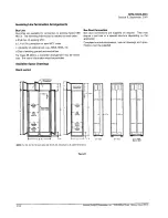
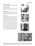
Figure 3
-
Rear view of unit showing stab assembly.
Figure 7
- Disconnect operating
handle modes listed from the
top downward: ON, TRIP, OFF,
PARK/ RESET
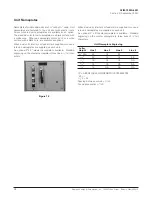
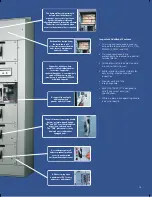
Unit Supports
Each plug-in unit is supported in the structures on a separator
angle and two shelf brackets. The angle and shelf brackets
can be moved easily to accommodate different size units by
removing only two screws. The shelf brackets guide the unit
to assure a positive engagement with the vertical bus. They
also provide for a positive TEST position. The unit cannot be
drawn out in one motion. The power stabs are disengaged in
TEST position, and two padlocks can be used to lock the unit
in TEST position safely.
Unit Racking
The unit is engaged to the vertical bus by use of a unique
racking lever mounted on the top barrier plate.
Once
engaged, the unit is held in place by the racking lever and a
screwdriver-operated locking latch in the bottom barrier plate.
Both devices are located near the front of the unit, away from
hazardous voltages.
Disconnect Operating Handle
The unit disconnect operating handle design shows ON, OFF,
and TRIP indication by color, position, and label. Regardless
of the distance or angle of viewing, the mode of operation is
readily distinguishable by color and position. A disconnect
operating handle is supplied on all MCC unit disconnect
devices through 600A.
The unique handle design allows the unit disconnect operat-
ing handle to be in the OFF position while maintaining the
mechanical door interlock feature. To open the unit door, the
disconnect operating handle is simply moved past the OFF
position to the PARK/RESET position.
Interlock Mechanisms
The disconnect operating handle is integrally mounted on the
unit and mechanically interlocked, so that the door cannot be
opened with the disconnect ON and the disconnect cannot
be closed with the door open. A unique interlock bar prevents
insertion or disengagement of the unit while the disconnect
is in the ON position.
The disconnect operating handle may be padlocked in the
OFF position with the door closed or open, with up to 3 pad-
locks. The unit may also be padlocked in the ON position by
drilling out a pilot hole in the handle and inserting one pad-
lock. Modification of the disconnect operating handle is not
available from the factory.
Figure 2
-
Shelf bracket.
Figure 6
-
Racking lever.
Figure 4
Locking latch: engaged.
Figure 5
Locking latch: disengaged.
Содержание TIASTAR SFIM-70020
Страница 63: ......
Страница 64: ......
Страница 65: ......
Страница 66: ......
Страница 67: ......
Страница 68: ......
Страница 69: ......
Страница 70: ......
Страница 71: ......
Страница 72: ......
Страница 73: ......
Страница 74: ......
Страница 75: ......
Страница 76: ......
Страница 77: ......
Страница 78: ......
Страница 79: ......
Страница 80: ......
Страница 81: ......
Страница 82: ......
Страница 83: ......
Страница 84: ......
Страница 85: ......
Страница 86: ......
Страница 87: ......
Страница 88: ......
Страница 96: ...4 ...
Страница 100: ...5 Today and tomorrow you ll know you have the very best ...
Страница 115: ...13 Siemens Energy Automation Inc ...
Страница 116: ...14 Siemens Energy Automation Inc ...
Страница 117: ...15 Siemens Energy Automation Inc ...


