background image

Siemens Energy & Automation, Inc.
1500 West Harvester
West Chicago, IL 60185
Tel: 630/231-6200
http://www.sea.siemens.com

© 2001 Siemens Energy & Automation, Inc.
Siemens is a registered trademark of Siemens AG.

Publication No. SFIS-70090-1201

Printed in the USA 

Содержание TIASTAR SFIM-70020

Страница 1: ...stribution Unit Ratings D Control Components E Appendix I General Specifications F Appendix II Definitions Terms and Reference Data G The Industrial Motor Control Center Siemens Energy Automation Inc 1000 McKee Street Batavia Illinois 60510 SFIM 7002A 0901 Supersedes SFIM 70020 TIASTAR Motor Control Center ...

Страница 2: ...ng FVC Full Voltage Contactor FVR Full Voltage Reversing 2S1W Two Speed One Winding 2S2W Two Speed Two Winding PW Part Winding RVAT Reduced Voltage Auto Transformer FCB Feeder Circuit Breaker DFCB Dual Feeder Circuit Breaker FDS Feeder Disconnect Switch DFDS Dual Feeder Disconnect Switch XFMR Transformer lighting LDCTR Load Center PNLBD Panel Board RVSS Reduced Voltage Soft Start Nordic VFD Variab...

Страница 3: ...Sizes 0 4 Molded case switch Sizes 5 and 6 Fuse clips for Class R fuses Starters Innova Plus Sizes 0 4 Bimetallic Ambient Compensated Overload Electrical starter seal in contact for 3 wire control Size 0 1 NO only Sizes 2 4 SPST Size 5 6 SPDT Control circuit terminals Type A Connect to component terminal Type Bd Bt C Unit stationary terminal blocks Load power terminals Type A Bd Connect to starter...

Страница 4: ...Unit Control Control Maximum Horsepower Starter Frame Unit Space Transformer Transformer 200V 230V 460 575V Size Size Height Factor VA VA Relay Timer 3 3 5 0 125 12 1 50 150 1 1 7 7 10 1 125 12 1 50 150 1 1 10 15 25 2 125 12 1 50 150 1 1 25 20 50 3 125 18 1 150 250 1 1 25 20 50 3 125 24 2 150 250 2 1 40 50 100 4 125 250 24 2 150 250 2 1 75 100 200 5 400 36 3 50d 150d 1 150 200 400 6 600 48s 4 150 ...

Страница 5: ...nation Starter Ratings and Dimensions FVNR High Density Full Voltage Non Reversing Unit With Circuit Breaker Standard Features Plug in unit Sizes 0 1 ETI Sizes 0 1 Starters Innova Plus Sizes 0 1 ESP100 Overload Electrical starter seal in contact for 3 wire control Size 0 1 NO only Control circuit terminals Unit stationary terminal blocks ...

Страница 6: ...vailable Features Standard Unit Size Control power transformer with fused secondary and dual fused primary Thermal magnetic circuit breaker 2 pilot devices mounted on unit device panel Surge suppressor Internal Circuit Breaker Interlock Extra starter auxiliary contacts in addition to NO seal in contact Clips Refer to tables below for maximum size control power transformer relays and timer addition...

Страница 7: ...inal Type Bd Bt C Unit stationary terminal blocks Load power terminals Type A Bd Bt C Electrical starter seal in contact for 3 wire control Size 0 1 NO only Qualifications Extra capacity control power transformer not available Current limiter attachment not available No room for relays or timers Maximum of four pilot devices per dual unit Maximum of 12 control and 3 power terminal points per start...

Страница 8: ...cuit breaker Barrier between starters Surge suppressors Handle interlocks operate with handle Extra starter auxiliary contacts in addition to NO seal in contact Communicating devices ASi SIMOCODE DP SAMMS Dual FVNR with ITE MCP Type ETI Disconnect Ratings and Space Requirements Standard Maximum ETI Unit Control Control Maximum Horsepower Starter Frame Unit Space Transformer Transformer 200V 230V 4...

Страница 9: ...andard Features Thermal magnetic circuit breaker Plug in unit Sizes 0 5 Fusible Switch Sizes 0 4 Molded case switch Sizes 5 and 6 Fuse clips for Class R fuses Contactor Innova Plus Sizes 0 4 Electrical starter seal in contact for 3 wire control Size 0 1 NO only Size 2 4 SPST Size 5 6 SPDT Control circuit terminals Type A Connect to component terminals Type Bd Bt C Unit stationary terminal blocks L...

Страница 10: ... power transformer with fused secondary and dual fused primary Pull apart control terminals Pull apart load terminals Sizes 0 2 4 pilot devices mounted on unit device panel Control relay Surge suppressor ETM Handle interlocks operate with handle Extra starter auxiliary contacts in addition to NO seal in contact Class J fuse clips Refer to tables for maximum size control power trans former relays a...

Страница 11: ... reversing electrical interlock per contactor Mechanical interlock on contactors Bimetallic Ambient Compensated Overload Starter Innova Plus Sizes 0 1 with vertical mechanical interlock Innova Plus Sizes 2 4 with horizontal mechan ical interlock Bimetallic OL Control circuit terminals Type A Connect to component terminal Type Bd Bt C Unit stationary terminal blocks Load power terminals Type A Bd C...

Страница 12: ... 7 7 10 1 30 60 18 1 50 150 2 1 10 15 25 2 60 60 24 2 50 150 2 1 25 30 50 3 100 100 36 3 150 250 2 1 40 50 100 4 200 200 54a 4 150 250 2 1 75 100 200 5 400 600 30x72a 6 50d 150d 2 2 Either or but not both a Fixed mounted unit s Fixed mounted unit space behind not available d Starter supplied with interposing relay s 200 230V applications Available Features Standard Unit Size Control power transfor...

Страница 13: ... Size 5 SPDT Mechanically interlocked starters Innova Plus Sizes 0 4 Bimetallic Ambient Compensated Overload 5 pole starter and 3 pole starter horizontally interlocked Size 2 vertical reversing starter and separate starter Size 3 4 horizontal reversing starter and separate starter Control circuit terminals Type A Connect to component terminal Type Bd Bt C Unit stationary terminal blocks Load power...

Страница 14: ... 3 100 100 48 4 150 250 2 1 40 50 100 30 40 75 4 200 200 72a 6 50d 250d 4 1 75 100 200 60 75 150 5 400 600 30x72a 5 50d 250d 2 1 a Fixed mounted unit d Starter supplied with interposing relay s 200 230V applications Auxiliary Contacts Extra Contact Extra Contact Starter Constant or Variable Torque Constant Horsepower Size High Low High Low Type 0 1 0 2 2 0 SPST NO or NC 2 4 4 2 2 4 SPST NO or NC 5...

Страница 15: ...Sizes 0 1 NO only Sizes 2 4 SPST Size 5 SPDT Bimetallic Ambient Compensated Overload Mechanical interlock on starters Starters Innova Plus Sizes 0 4 Sizes 0 4 Innova Plus consisting of 2 starters horizon tally interlocked Sizes 5 2 starters with vertical mechanical interlock Control circuit terminals Type A Connect to component terminal Type Bd Bt C Unit stationary terminal blocks Load power termi...

Страница 16: ...60 24 2 50 150 2 1 25 30 50 20 25 40 3 100 100 36 3 150 250 2 1 40 50 100 30 40 75 4 200 200 54a 4 50d 250d 1 1 75 100 200 60 75 150 5 400 600 30x72a 6 50d 250d 2 2 a Fixed mounted unit d Starter supplied with interposing relay s 200 230V applications Auxiliary Contacts Starter Extra Contacts Size Hi Low Type 0 1 3 3 SPST NO or NC 2 4 2 2 SPST NO or NC 5 2 2 SPDT NO NC Available Features Standard ...

Страница 17: ...hes Sizes 4 5 Molded case switch Size 4 on 230V Fuse clips for Class R fuses Starters Innova Plus 0 4 Bimetallic Ambient Compensated Overload Electrical starter interlocks NO interlock supplied on 1M for 3 wire control Sizes 1 NO only Sizes 2 4 SPST Sizes 5 SPDT Control circuit terminals Type A Connect to component terminal Type Bd Bt C Unit stationary terminal blocks Load power terminals Type A B...

Страница 18: ...V 230V 460 575V Size Size Size Height Factor VA VA Relay 55BA 10 10 15 1 60 60 24 2 150 250 2 1 20 25 40 2 100 100 30 2 150 250 2 1 40 50 75 3 200 200 48 4 150 250 2 1 75 75 150 4 400 400 72a 6 50d 250d 1 1 150 150 350 5 600 600 30x72a 6 50d 250d 2 2 a Fixed mounted unit d Starter supplied with interposing relay s 200 230V applications Auxiliary Contacts Starter Extra Contacts Size Per Starter Typ...

Страница 19: ...interlock 3 pole contactor 2S Bimetallic Ambient Compensated Overloads Auto Transformer NEMA medium duty 3 coil 50 65 80 taps Class F insulation minimum Mounted across bottom of structure Electrical starter interlocks NO on 2S R for 3 wire control Sizes 2 4 SPST Sizes 5 6 SPDT Control circuit terminals Type A Connect to component terminal Type Bd Bt C Unit stationary terminal blocks Load power ter...

Страница 20: ... Unit Space Transformer Transformer 200V 230V 460 575V Size Size Size Height Factor VA VA Relay Timer 10 15 25 2 60 60 42a 3 150 250 2 1 25 30 50 3 100 100 48a 4 150 250 2 1 40 50 100 4 200 200 60a 6 50d 250d 75 100 200 5 400 600 30x72s 6 50d 250d 1 1 150 200 350 6 600 600 30x72s 6 50d 250d 2 400 6 800 800 50x72 sf 6 50d 250d a Fixed mounted unit s Fixed mounted unit space behind not available d S...

Страница 21: ...ches Sizes 0 3 Molded case switches Sizes 4 5 Starters Innova Plus 0 4 Bimetallic Ambient Compensated Overloads Control circuit terminals Type A Connect to component terminal Type Bd Bt C Unit stationary terminal blocks Electrical starter interlocks NO interlock For 3 wire control Sizes 2 4 SPST Sizes 5 6 SPDT Load power terminals Type A Bd Connect to starter terminals Type Bt C Sizes 0 3 stationa...

Страница 22: ...orsepower Starter Switch Clip Unit Space Transformer Transformer 200V 230V 460 575V Size Size Size Height Factor VA VA Relay Timer 20 25 40 2 100 100 48 4 150 250 2 2 40 50 75 3 200 200 60 5 150 250 2 1 60 75 150 4 400 400 72a 6 50d 250d 2 1 150 150 300 5 600 600 30x72a 6 50d 250d 4 2 a Fixed mounted unit d Starter supplied with interposing relay s Auxiliary Contacts Starter Extra Contacts Size Pe...

Страница 23: ...ion Standard Features Sizes 0 6 circuit breaker Sizes 0 5 fusible switch Fusible switches Sizes 0 3 Molded case switches Sizes 4 5 Starters Innova Plus 0 4 Bimetal Ambient Compensated Overloads Control circuit terminals Type A Connect to component terminal Type Bd Bt C Unit stationary terminal blocks Electrical starter interlocks NO interlock For 3 wire control Sizes 2 4 SPST Sizes 5 6 SPDT Load p...

Страница 24: ...r Switch Clip Unit Space Transformer Transformer 200V 230V 460 575V Size Size Size Height Factor VA VA Relay Timer 20 25 40 2 100 100 36 3 150 250 2 1 40 50 75 3 200 200 48 4 150 250 2 1 60 75 150 4 400 400 72a 6 50d 250d 2 1 150 150 300 5 600 600 30x72a 6 50d 250d 4 2 a Fixed mounted unit d Starter supplied with interposing relay s Auxiliary Contacts Starter Extra Contacts Size Per Starter Type 2...

Страница 25: ...es 30A through 200A are mounted in plug in units Switches above 200A are fixed mounted and consist of molded case switches and separate fuse blocks Dual mounted fusible switches are available 30A and 60A with clips of same rating Fuse clips are Class RK dimensions for 30 600A FeederTap Circuit Breakers and Fusible Switches Disconnect Ratings and Space Requirements Unit Fuse Unit Max Height Switch ...

Страница 26: ... primary currents 125 lp for lp greater than 9A 167 lp for lp less than 9A 300 lp for lp less than 2A In addition to primary protection secondary protection must be supplied if the transformer secondary is 3 or 4 wire dual voltage Secondary protection is not required if the trans former is 2 wire single voltage secondary Description of Standard Transformers Single Phase Transformers 1KVA thru 2KVA...

Страница 27: ...pending on number of cir cuits Main lug only 100 and 225A Main circuit breaker 100 and 225A 12 to 42 circuits 10 000A 240V short circuit rating UL listed Disconnect Ratings and Space Requirements Circuit Breaker Panel Boards Main Bus Unit Number Breaker Rating Height Circuits Type Amps Amps Inches 18 1ø 3W 100 30 30 1ø 3W 225 36 42 1ø 3W 225 42 18 3ø 4W 100 30 30 3ø 9W 225 36 42 3ø 4W 225 42 18 1ø...

Страница 28: ...ks or other mechanical linkages The spring assures quick precise opening of the contacts Pressure Clamp Terminals Starter terminals are designed for ease of wiring without bending or looping wires All mounting screws and pressure terminals face clearly forward making them easily accessible with a screwdriver Single Voltage Coil Magnetic coils are carefully wound and then encapsulated in epoxy Enca...

Страница 29: ...ed coil magnet armature and contacts This design provides these benefits Innova Plus Magnetic Starters are available in sizes 0 1 2 3 and 4 Figure 3 Less Contact Bounce Contact bounce is virtually eliminated by the combination of the 45 degree angle and the wedge action contact configuration Lower movable con tacts close in a vertical position and upper movable contacts close in a hor izontal posi...

Страница 30: ... The motor current is detected in each phase via integral cur rent transformers and is continuously monitored by a micro processor A TEST RESET button allows the user to test the unit s functions during operation without changing the state of the overload contacts A self monitoring feature causes the unit to trip when an internal fault occurs Remote or auto matic reset of an overload trip is accom...

Страница 31: ... external trip incom plete sequence ground fault and internal CPU fault In addi tion SAMMS can provide statistical motor data including the total elapsed motor running time and number of starts and overload trips Typical motor control devices such as timers relays pushbuttons and selector switches are replaced by SAMMS software and pushbuttons and indicators on the unit control panel An optional c...

Страница 32: ... 100 50 4 200 2 00 Solid State Controls As an industrial technology company Siemens Controls is capable of providing a wide variety of solid state devices in motor control centers Typical components may include Soft start Controllers Variable Frequency Drives and Programmable Logic Controllers The TIASTAR motor control center is designed to mount these and many other user specified solid state con...

Страница 33: ...ives MICROMASTER and MIDIMASTER drives 6SE32 are built to be the inverter of choice for their innovative design simplici ty technology and workmanship They offer an impressive array of performance and flexibility features not common in standard general purpose drives These drives are available with Sensorless Vector Control that provides the ultimate in torque developing power to tame any tough ap...

Страница 34: ...se of a pilot light Excess Capacity CPT VA Rating Excess VA Rating Inrush Capacity Required Capacity FVNR Above For 100 Inrush of Starter Standard Starter VA Requirement Standard Size VA Rating Required Extra VA Transformer 0 50 25 150 218 218 1 50 25 150 218 218 2 50 24 150 218 218 3 150 124 250 310 1130 4 150 75 250 957 1130 5d 50 25 150 133 218 6 150 90 250 350 1130 d Starter supplied with inte...

Страница 35: ...p An optional 120V high intensity LED lamp is optional 22mm transformer type pilot lights are not available in Siemens motor control centers Class 52 30mm Metal Siemens Class 52 chrome pilot devices are optional on TIAS TAR motor control centers Class 52 pilot devices are UL list ed and CSA certified and have a NEMA 4 environmental rating Contact blocks are rated for 10A continuous at 600VAV NEMA ...

Страница 36: ...ion by LED voltage indication by LED Actuator Sensor Interface AS Interface Siemens motor control centers utilize AS Interface Slimline to reduce the amount of interconnection wiring required between motor control center units and a PLC Slimline mod ules incorporate all of the communication benefits of AS Interface in a physical package that uses screw terminations rather than the vampire connecti...

Страница 37: ...ts is anoth er exclusive Siemens Controls feature By having the terminal blocks pivot out into the vertical wireway it allows greater wiring accessibility The swing plate and terminal blocks are pivoted back into the unit when not being worked on Stationary Terminal Blocks Clamping the wire between a tang and a collar provides the following advantages 1 No twisted off strands 2 A constant locking ...

Страница 38: ...ill be supplied with stationary non pull apart load terminal blocks Load terminals are white in color Type C Wiring Type C wiring uses stationary type terminal blocks Their stan dard location is in the top 12 horizontal wireway C terminals may also be located in the bottom 6 horizontal wireway Three rows of terminals for control and load may be mounted at the top Space is available for 42 terminal...

Страница 39: ... 14 gauge 19 strand copper 105iC 600V PVC Power Wiring Sized to suit maximum HP rating of unit 12 gauge to 2 gauge 19 strand copper 105iC 600V PVC 1 gauge to 500 MCM 19 strand to 37 strand copper 105iC 600V PVC Standard Color Coding of Wires AC Control all voltages Red DC Control all voltages Blue AC Power all voltages Black Line Side CPT Black Equipment Ground Green Current Carrying Neutral White...

Страница 40: ...lied in each vertical section A separate hinged door shall cover the vertical wireway 2 1 4 Each standard structure shall be supplied with 12 inch top and six 6 inch bottom horizontal wire ways that are continuous for the entire length of the MCC The minimum horizontal wireway opening between sections is 40 square inches for the top and 30 square inches for the bottom horizontal wireway A hinged d...

Страница 41: ... All connecting hardware shall be designed to be tightened from the front of the MCC without applying any tools to the rear of the connection Units 4 0 Plug in units shall connect to the vertical bus by means of self aligning tin plated copper stab on connectors provided with spring steel back up springs to insure pos itive connection to the vertical bus 4 0 1 When vertical ground bus is specified...

Страница 42: ...or switches are specified The devices shall be mounted in a formed metal device panel that is capable of accepting four 4 such devices in any combination The device panel shall be secured to the unit door for normal operation or mounted on the plug in unit as required for unit removal and bench testing 4 2 1 Pilot devices when specified shall be 22 mm in diameter rated for NEMA 4 IP67 applications...

Страница 43: ...ned as Feeder Tap Units per ICS 2 322 A feeder tap unit shall include externally operable circuit dis connecting means and branch circuit overcurrent protection principally used for non motor loads Two sets of circuit dis connecting means with branch circuit overcurrent protection may be mounted in a single compartment to form a dual unit In addition a control center may contain any combination of...

Страница 44: ...ed Units Class II motor control centers shall be the same as Class I motor control centers with the addition of manufacturer fur nished electrical interlocking and wiring between units as specifically described in overall control system diagrams sup plied by the purchaser In addition to the drawings furnished for Class I motor control centers the manufacturer shall furnish drawings that indicate f...

Страница 45: ...nd is by design one of the factors determining the maximum fault current bracing and limitation of the maximum bus which may be utilized Vertical Bus Support maintains the vertical bus in its posi tion and provides a means of bracing the vertical bus for fault currents Design will limit the vertical bus size and configura tion Bus Barriers may be of insulating or non insulating material but in eit...

Страница 46: ...isconnects Current limiting fuses can be supplied that will limit available short circuit current to the MCC See page G6 for interrupting ratings classification Starter Units Starter units should be selected to meet the required function and horsepower See combination starter rating and dimen sion pages D2 through D17 for ratings These ratings are for normal duty Jogging or plugging applications w...

Страница 47: ...recommendations below are based on the Motor Control Center being located in a 40IC maximum ambient For ambients greater than 40IC or altitudes above 6000 feet contact Siemens for recommended ratings Motor Control Centers UL 845 and NEMA ICS2 322 24 require that all structures and units in an MCC carry a short circuit rating equal to or exceed ing the available short circuit current of the system ...

Страница 48: ... Circuit Breakers Startera or Contactor Rating Size Type 240V 480V 600V 0 6 ETI 42K 100KA 42K 100KA 25K 0 6 CED CFD 100K SCJD SCLD Mains and Feeders Ratings in KA Type Frame 240V 480V 600V ED6 125 65 25 18 HED4s 125 100 42 HHED6 125 100 65 18 CED6 125 100 100 100 FD6 250 65 35 22 HFD6 250 100 65 25 HHFD6 250 100 100 25 CFD6 250 100 100 100 JD6 400 65 35 25 HJD6 400 100 65 35 HHJD6 400 100 100 50 S...

Страница 49: ...2 30 22 40 2 28 40 42 50 54 100 3 68 100 80 125 4 104 150 130 150 154 250 5 192 250 248 400 312 400 6 360 400 480 600 Starter Size FLA MCP 230V 60Hz 2 4 3 3 5 5 0 4 6 10 6 6 10 7 5 10 10 6 25 1 16 7 30 24 2 40 2 30 8 50 46 2 100 3 59 4 100 74 8 125 4 88 125 114 150 143 250 5 169 250 211 400 273 400 6 343 600 396 600 Starter Size FLA MCP 208V 60Hz 2 5 3 3 7 5 0 4 8 10 6 9 10 7 8 25 11 0 25 1 17 5 3...

Страница 50: ...40 4 40 3 25 100 4 50 3 40 4 30 100 4 50 4 50 3 40 150 4 100 3 50 4 50 250 2 100 4 100 3 60 250 4 100 4 100 3 75 250 6 150 4 100 4 100 400 4 250 3 150 4 125 400 6 250 4 250 3 150 600 4 250 5 250 3 200 600 7 400 4 250 6 250 400 6 400 4 300 600 4 400 5 350 600 4 400 5 400 600 6 600 4 A Continuous amps I T E Type ETI Setting Positions Cont Trip Settings Positions Amps LOW 2 3 4 5 6 7 HI 1 2 6 4 5 6 7...

Страница 51: ...0 250 300 350 400 1 1 15 1 6 15 2 1 15 0 3 15 3 4 15 4 8 15 7 6 15 1 11 0 20 14 25 21 35 2 27 45 34 60 40 70 3 52 80 65 100 77 125 4 96 150 124 200 156 250 5 180 300 240 400 302 500 6 361 600 414 700 477 800 Starter Size FLA 460V 60Hz 0 81 15 1 21 15 2 15 0 2 5 15 3 5 15 5 15 7 5 15 1 11 0 20 14 25 21 35 2 28 45 35 60 40 70 3 55 90 64 100 80 125 4 100 175 135 250 165 250 5 200 300 260 400 325 500 ...

Страница 52: ...2 5 4 5 3 7 5 6 6 0 4 8 7 8 6 9 10 12 7 8 12 15 11 0 17 5 20 1 17 5 25 35 25 3 40 50 2 32 2 50 60 48 3 70 90 3 62 1 90 110 78 2 110 150 4 92 125 175 120 175 225 150 225 300 5 177 250 350 221 350 400 285 450 500 6 359 500 700 414 600 800 Starter Size FLA Time Delay HP 1 1 2 3 5 7 10 15 20 25 30 40 50 60 75 100 125 150 200 250 300 350 400 Time Delay Non Delay Time Delay Starter Size Non Delay Time D...

Страница 53: ...ng Current Limiting Current Current Limiting Current Current Limitinga Time Delaya Time Delaya Limiting Time Delay Limiting Limiting Rejection Type No No No Yes Yes Inherent Inherent Manufacturer Bussman KTN Bussman FRN Bussman LPN RK Bussman FRN R Bussman JKS Bussman KTU Designations Bussman KTS Bussman FRS Bussman KTS R Bussman FRS R Shawmut A4J Shawmut A4BY Shawmut A2D Shawmut TR Shawmut A4Bt S...

Страница 54: ...0 123 130 E32 400 131 140 E33 400 141 155 E34 400 156 166 E36 400 167 177 E37 400 178 193 E38 400 Size 5 only D25651 5 Size 6 166 195 E27 600 196 217 E28 600 218 229 E29 600 230 245 E31 600 246 261 E32 600 262 281 E33 600 282 311 E34 600 312 331 E36 600 332 355 E37 600 356 387 E38 600 388 419 E39 600 420 467 E41 600 468 500 E42 600 D25665 3 Full Load Motor Amps Heater Code No Max Rat of Prot Devic...

Страница 55: ...rent in common wire N 1 41 X that in the other 2 lines 50 Hz multiply 60 Hz value X 1 20 25 Hz 1500 RPM amps N amps of 60 Hz 3600 RPM 25 Hz 750 RPM amps N amps of 60 Hz 1800 RPM Service factor 1 0 N amps X 0 9 50i 55iC motor N amps X 0 9 Single Phase Motor FLA The single phase full load amps of the same horsepower volt age and speed vary over wide ranges The following table conforms with table 430...

Страница 56: ...230V 380V 415V 460V 575V KW HP FLA FLA FLA 50Hz FLA 50Hz FLA FLA FLA 0 25 1 39 1 2 0 6 0 84 0 33 1 3 1 69 1 46 0 73 0 58 0 37 0 5 2 5 2 4 2 1 3 81 1 1 9 0 55 0 75 3 7 3 5 3 2 1 8 1 21 1 6 1 3 0 75 1 4 8 4 6 4 2 2 3 2 2 1 1 7 1 1 1 5 6 9 6 6 6 0 3 3 2 5 3 2 4 1 5 2 7 8 7 5 6 8 4 3 3 5 3 4 2 7 2 2 3 11 10 6 9 6 6 1 5 4 8 3 9 3 7 5 17 5 16 7 15 2 9 7 7 5 7 6 6 1 5 5 7 5 25 3 24 2 22 14 11 11 9 7 5 10...

Страница 57: ...clothing etc in accordance with established safety practices c is trained in rendering first aid SIGNAL WORDS The signal words Danger Warning and Caution used in this manual indicate the degree of hazard that may be encountered by the user These words are defined as Danger Indicates death or serious injury will result if proper precautions are not taken Warning Indicates death serious injury or pr...

Страница 58: ...pose Indoor B6 NEMA 2 Drip proof Indoor B6 NEMA 12 Industrial Use Indoor B7 NEMA 3R Rainproof Outdoor B7 Bus and Bus Bracing Horizontal Main Bus B7 Vertical Bus B7 MCC Shutter Mechanism B8 Neutral Bus B8 Ground Bus B8 Bus Drawings Available Locations Of Ground And Full Length Neutral B9 Bus Mounting Dimensions B9 Typical Stab on Conections for Back to Back Sections B10 Bus Drawing B10 Mounting of ...

Страница 59: ... Combination Starter Ratings and Dimensions FVNR Full Voltage Non Reversing Unit with Fusible Switch or Circuit Breaker D2 3 FVNR High Density Full Voltage Non Reversing Unit with Circuit Breaker D4 5 Dual FVNR Full Voltage Non Reversing Unit with Fusible Switch or Circuit Breaker D6 7 Combination Contactor Ratings and Dimensions with Fusible Switch or Circuit Breaker D8 9 FVR Full Voltage Reversi...

Страница 60: ...y CPT VA Rating E7 Fuse Selection Control PowerTransformer E7 Pilot Controls E8 Pilot Devices E8 3SB3 22mm Plastic E8 Class 52 30mm Metal E8 Relays E9 3RH11 E9 3RP15 Timing Relay E9 Actuator Sensor Interface AS Interface E9 Terminal Blocks and Wiring E10 Control Terminal Blocks E10 Swing Plate E10 Stationary Terminal Blocks E10 Pull Apart Terminal Blocks E10 Special Terminal Blocks E10 Load Termin...

Страница 61: ...arter Units G4 FeederTap Units G4 FeederTap Circuit Breakers or Fusible Disconnects G4 NEC Requirements for Lighting Panels G4 384 14 Lighting and Appliance Branch Circuit Panelboard G4 384 15 Number of Overcurrent Devices on One Panelboard G5 384 16 Overcurrent Protection G5 Short Circuit Rating and Equipment Selection Information Introduction G5 Motor Control Centers G5 Short Circuit Ratings for...

Страница 62: ...tandard Fuse Classifications G11 E Standard Trip Heater Elements for Ambient Temp Comp Bimetal Relays G12 HeaterTablesG12 14 Additional Information Part Winding Starter Heater Selection G13 Bimetal Overload Relays G13 Formulas for Obtaining FLA of Other Motors G13 Single Phase Motor FLA G13 Approximate AC Motor Amps G14 ...

Страница 63: ......

Страница 64: ......

Страница 65: ......

Страница 66: ......

Страница 67: ......

Страница 68: ......

Страница 69: ......

Страница 70: ......

Страница 71: ......

Страница 72: ......

Страница 73: ......

Страница 74: ......

Страница 75: ......

Страница 76: ......

Страница 77: ......

Страница 78: ......

Страница 79: ......

Страница 80: ......

Страница 81: ......

Страница 82: ......

Страница 83: ......

Страница 84: ......

Страница 85: ......

Страница 86: ......

Страница 87: ......

Страница 88: ......

Страница 89: ...ce of a racking lever for racking the unit into and out of the engaged position A sup plementary handle on the front of the unit aids in installation Plug in Unit Construction Tin plated copper power stabs are standard on all plug in units The power stabs engage the vertical power distribution bus when the units are installed in the structure They are enclosed in a two piece glass filled polyester...

Страница 90: ...onnect operating handle design shows ON OFF and TRIP indication by color position and label Regardless of the distance or angle of viewing the mode of operation is readily distinguishable by color and position A disconnect operating handle is supplied on all MCC unit disconnect devices through 600A The unique handle design allows the unit disconnect operat ing handle to be in the OFF position whil...

Страница 91: ...Class 52 pilot devices All unused pilot device mounting holes are covered by a snap in hole plug It is mounted on the unit door for nor mal operation but can be easily removed from the door and mounted on the plug in unit for unit removal and testing The pilot device panel attaches to the unit door with two captive screws and stays with the door when open giving maximum access to the unit for trou...

Страница 92: ...rs or feeders are supplied two sepa rate unit nameplates are supplied on each unit An optional 2 x 6 master nameplate is available Standard engraving on the master nameplate is three lines 1 2 tall char acters When dual units starters or feeders are supplied two sepa rate unit nameplates are supplied on each unit An optional 2 x 6 master nameplate is available Standard engraving on the master name...

Страница 93: ...uns through transformer to customized power distribution system ATIASTAR Motor Control Center safely controls power to assembly lines TheTIASTAR Motor Control Center maintains critical systems during off hours TIASTAR with SISystem Onboard monitors operations ...

Страница 94: ...izing the high starting current and torque associated with across the line motor starting Sizes range from fractional up to 800 horsepower Programmable Logic Controllers PLC Available modular designs range from16 l O to 288 l O and up to 10 000 l O including communication and analog capabilities ESP100 ESP100 starter with solid state overloads trip within three seconds of phase loss Heater free de...

Страница 95: ...SISystem Smart Integrated Solutions System 3 ASI Cable Profibus Communication Motors Pumps and Valves Electronic Sensors ...

Страница 96: ...4 ...

Страница 97: ...at they are fully engaged with the vertical bus An interlock with the disconnect device ensures that a plug in unit is not inserted or removed from the vertical bus when the unit is energized A positive stop in the TEST position indicates that a plug in unit is fully withdrawn from the vertical bus Pilot devices are mounted on a sturdy formed metal panel attached with two captive screws to the MCC...

Страница 98: ...pection a breeze The barrier is easily removed when access to the horizontal bus is required Horizontal bus design keeps the bus in the top 12 of the structure never behind units for easy maintenance and accessibility Copper bus and heavy duty insulators safely distribute power to sections Copper bus standard throughout is conservatively rated at 50 degree rise and provides up to an optional 100 0...

Страница 99: ...infrared scanning isolates horizontal bus bars from the top horizontal wireway Available horizontal bus options include 600 through 2 500 amp ratings and available vertical bus options include ratings ranging from 300 to 600 amp Also vertical ground bus is available with load ground terminals reducing installation costs when using multi conductor cables A feature others should adapt because it is ...

Страница 100: ...5 Today and tomorrow you ll know you have the very best ...

Страница 101: ...introduction of its advanced SISystem Smart Integrated Solutions System provides you with seamless control of your physical plant by fusing ASI PROFIBUS and ACCESS as well as most legacy systems into a robust fully integrated management system Whatever your requirements motor control centers panelboards transformers switchboards orTIA systems you will find Siemens SISystem compliant products smart...

Страница 102: ... networks the know how of employees in over 190 countries to benefit customers and win new business and live up to the motto Siemens Global Network of Innovation To learn more about Siemens please visit us at www siemens com We thank you for your consideration and your business Electricity enters building via municipal power lines 1 Siemens Energy Automation Inc Siemens Furnas Controls Business Un...

Страница 103: ...Siemens Energy Automation Inc SFIS 70090 1201 December 2001 TIASTAR Motor Control Center Installation And Maintenance Instructions For Units Only ...

Страница 104: ... hat safety glasses or face shields flash clothing etc in accordance with established safety practices c is trained in rendering first aid SIGNAL WORDS The signal words DANGER WARNING and CAUTION used in this manual indicate the degree of hazard that may be encountered by the user These words are defined as DANGER For the purpose of this manual and product labels DANGER indicates an imminent ly ha...

Страница 105: ...between the parties is the sole warranty of Siemens Any statements contained herein do not create new warranties or modify the existing warranty Table of Contents Receiving 4 Addition And Replacement Of Control Units 4 Adding To A Blank Unit Space 4 Replacement With A Unit Of The Same Size 4 Rearranging Control Units Of Different Sizes 4 Outgoing Power And Control Wiring 5 Pre Operation Checks 5 6...

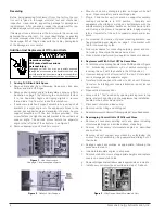
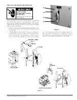
Страница 106: ...mounting brackets see fixed mounted panel diagram on page 7 Use bracket with tab for top mounting holes h Follow procedures for connecting outgoing power and con trol wiring Mount pilot device panel on door i Close door and perform all pre operation check procedures 2 Replacement With A Unit Of The Same Size a Put disconnect operating handle in the PARK position Figure 13 Interlocking mechanism wi...

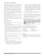
Страница 107: ... motor 6 Check all heater elements to insure that they are properly installed 7 Check all timers for proper time interval setting and contact operations 8 If HMCPs are used adjust as follows a Determine motor full load current from the motor name plate data Refer to the table and determine the appro priate setting position Use screwdriver to set indicator on adjustment screw to the appropriate pos...

Страница 108: ...clamp spring E will compress against bar F when the bolt is drawn tight 3 Slide carriage bolt B through the one side of the clamp assembly and tie bar until it protrudes through the other side of the clamp assembly Fasten with washer C and torque nut D to bolt B securing to 21 ft lbs 4 Repeat steps 1 3 for all phases 6 Siemens Energy Automation Inc Figure 4 Note The white side of clamping spring s...

Страница 109: ...er 11 Back plate 12 Top barrier plate 13 Pilot device panel mounting hole for mounting panel to unit to facilitate removing unit without disconnecting wires see accompanying photo Parts Illustrations Key to Unit Supports 1 Pin type door hinge 2 Separator angle 3 Shelf bracket 4 Termination for motor ground cable optional 5 Unit support mounting screw 6 Unit stab hole cover 7 Intermediate Angle Spe...

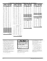
Страница 110: ...6 16 6 70 E50 15 6 71 7 54 E51 15 7 55 8 29 E52 15 8 30 8 99 E53 15 9 00 9 85 E54 15 9 86 10 4 E55 15 10 5 12 0 E56 15 12 1 13 6 E57 30 Size 1 only D25385 7 8 Siemens Energy Automation Inc E Standard Trip Heater Elements for Ambient Temp Comp Bimetal Relays Heaters shown in the table provide a max imum trip rating of 125 of the motor nameplate and amps which is suitable for 40 C motors For all oth...

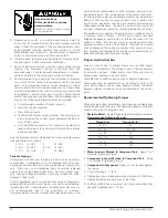
Страница 111: ...ting hinge if present in the 6 space 2 Install the unit support bracket per Adding To A Blank Unit Space on page 4 3 Locate and install the new hinge with the two mounting screws 4 Install the door using two new hinge pins supplied with the unit Unit Access For Maintenance 1 Remove the unit from the structure 2 Loosen screw B shown in Figure 12 3 Lift the handle bracket and pull forward to disenga...

Страница 112: ...eaners are not recommended due to the possibility of residues Compressed air is not recommended for cleaning because it will only distribute contaminants on other surfaces and may dam age delicate parts The inside bottom of the motor control cen ter should also be cleaned including removal of any hardware or debris so that any new or unusual wear or loss of parts occur ring after the inspection ma...

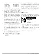
Страница 113: ...r or in the test position 2 The adjustable link rod can adjust to increase or decrease its overall length by rotating the sleeve By rotating the sleeve clockwise the length is increased and by rotating it counter clockwise the length is decreased A hex nut is provided as part of the adjustable link rod and is tightened against the sleeve to prevent it from going out of adjustment The hex nut must ...

Страница 114: ... previous adjustments have not been adverse ly effected 9 In the case of both the circuit breaker and disconnect switch the adjustment should be such they turn on with the knob no closer the 1 8 away from the escutcheon Note Always use two wrenches when loosening adjusting or tightening the adjustable link rod One wrench adjusts the hex sleeve while the second wrench holds the hex nut A provision ...

Страница 115: ...13 Siemens Energy Automation Inc ...

Страница 116: ...14 Siemens Energy Automation Inc ...

Страница 117: ...15 Siemens Energy Automation Inc ...

Страница 118: ...ion Inc 1500 West Harvester West Chicago IL 60185 Tel 630 231 6200 http www sea siemens com 2001 Siemens Energy Automation Inc Siemens is a registered trademark of Siemens AG Publication No SFIS 70090 1201 Printed in the USA ...

Отзывы: