G4
Siemens Energy & Automation, Inc. 1000 McKee Street Batavia, Illinois 60510
SFIM-7002A-0901
Section G, September, 2001
Future Unit Space
- unit space specified and equipped to
accept a future unit.
Blank Unit Space
- unit space not equipped to accept a
future unit.
Unusable Unit Space
- unit space not suitable to accept a
future unit.
Standard Drawings
- arrangement drawings and wiring dia-
grams prepared using manufacturer’s standard drawing sizes,
device symbols and identification, and numbering designa-
tion.
Custom Drawings
- manufacturer’s drawings made to meet
user custom requirements.
Protective Devices
Motor control centers must be properly protected against
overloads and fault currents. The protective device can be
located in the MCC or ahead of the MCC. It must have a
short circuit rating equal to or larger than the available short
circuit current at its line terminals.
Fault currents will vary from a bolted fault which would allow
maximum available short circuit current to low level arcing
faults that will not draw enough current, to trip the main.
These low level faults cannot be assumed to be self extin-
guishing and can cause considerable damage at the point of
the fault. Additional protective equipment, such as ground
fault relays on grounded systems, is required to protect the
MCC against low level fault currents.
Standard thermal magnetic main circuit breakers are rated the
same as the horizontal bus rating. These breakers will carry
80% of their continuous rating without tripping.
If a circuit breaker rated at 100% is required, it must be listed
for 100% use (typically these breakers are used in ventilated
enclosures). These breakers can be rated the same as the the
horizontal bus since the bus is rated to carry 100% of its cur-
rent continuously.
Main Circuit Breakers
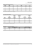
Thermal magnetic molded case breakers are used for mains
in the MCC (See pages G6, for interrupting ratings). The cur-
rent limiting characteristics of the main circuit breaker cannot
be used to increase the short circuit rating of the individual
units in the MCC.
Main Fusible Disconnects
Current limiting fuses can be supplied that will limit available
short circuit current to the MCC (See page G6 for interrupting
ratings classification).
Starter Units
Starter units should be selected to meet the required function
and horsepower (See combination starter rating and dimen-
sion pages D2 through D17 for ratings.) These ratings are for
normal duty. Jogging or plugging applications will reduce
these ratings (See application data, Siemens-Furnas Industrial
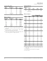
Control Catalog.) The starter unit’s protective device is sized
for horsepower using FLA current in NEC table 430-150.
Select respective ETI, thermal magnetic breaker, or fuses per
selection charts. Note that these charts are based on sizing
devices for short circuit protection of the unit and motor cir-
cuit. Running protection is obtained using overload relays.
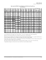
Heater coils are to be selected using motor nameplate data.
(The FLA listed in NEC 430-15 should not be used.)
Specific heaters are selected using the chart on page G12
depending on type of overload relays used and motor name-
plate data.
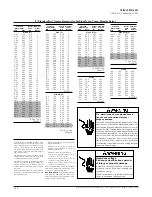
If AC motor amps and other data are not available from motor
nameplate, see Table G14 (see Note.) For motors other than T
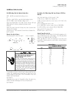
frame with 1.15 service factor, see formulas for obtaining FLA
of the motor, page G15. Per NEC, heater coil selection
should be checked with actual motor nameplate data before
energizing motor.
Combination Starter Units
The short circuit rating of a combination starter is determined
by test. The rating of a fusible unit is based on no over-fusing
on time delay fuses and one size oversize on non-delay Type
J fuse (See page G10-11).
Feeder Tap Units
Feeder tap units must have a short circuit rating that equals or
exceeds their available short circuit. See table page G6 for
short circuit rating.
Feeder Tap Circuit Breaker or Fusible Disconnect
Thermal magnetic trip or fuses should be sized for 125% of
continuous load. If fusible disconnect, the minimum continu-
ous rating of the disconnect must be sized at 115% of load.
NEC Requirements for Lighting Panels
384-14: Lighting and Appliance Branch Circuit Panelboard
A lighting and appliance branch circuit panelboard is one hav-
ing more than 10% of its overcurrent devices rated 40A or
less, for which neutral connections are provided.
Содержание TIASTAR SFIM-70020
Страница 63: ......
Страница 64: ......
Страница 65: ......
Страница 66: ......
Страница 67: ......
Страница 68: ......
Страница 69: ......
Страница 70: ......
Страница 71: ......
Страница 72: ......
Страница 73: ......
Страница 74: ......
Страница 75: ......
Страница 76: ......
Страница 77: ......
Страница 78: ......
Страница 79: ......
Страница 80: ......
Страница 81: ......
Страница 82: ......
Страница 83: ......
Страница 84: ......
Страница 85: ......
Страница 86: ......
Страница 87: ......
Страница 88: ......
Страница 96: ...4 ...
Страница 100: ...5 Today and tomorrow you ll know you have the very best ...
Страница 115: ...13 Siemens Energy Automation Inc ...
Страница 116: ...14 Siemens Energy Automation Inc ...
Страница 117: ...15 Siemens Energy Automation Inc ...


