Scale parameters and functions
8.4 Calibration procedure
SIWAREX WP231
Manual, 07/2014, A5E31238908A-02
77
8.4
Calibration procedure
8.4.1
Calibration with calibration weights
The incoming analog measured value from the load cells is converted into a digital value in
an analog-to-digital converter. A weight is calculated using this digital value. This weight is
then used by all weighing module functions for messages and for determining the status.
The characteristic curve of the measuring system must be defined before the weight can be
calculated from the digital value. In the simplest case, the characteristic curve is defined with
points 0 and 1. The first working point (point 0) is defined by the empty scales (no load) at
their own weight. The load cells return a voltage measurement to the weighing module as a
result of the weight of the scales themselves. Following analog-to-digital conversion of the
measured voltage, the zero point is assigned to the digital value (calibration digits for the
zero point).
If the scales are loaded with a defined calibration weight (e.g. 50% of the measuring range),
the new digital value returned by the analog-to-digital converter is assigned the calibration
weight.
The characteristic curve can also be determined with a third point, which must be higher than
point 1.
Make sure that the difference between two calibration weights is at least 40 000 digits, as the
calibration command may otherwise be rejected.
The calibration procedure involves the following steps:
●
Define the calibration weight and other parameters of the DR 3 data record.
●
Transfer the DR 3 data record to the scales.
●
Trigger "Calibration weight 0 valid" for empty scales.
●
Load the scales with the defined calibration weight.
●
Trigger "Calibration weight 1 valid".
●
Transfer data record DR 3 from the scales to SOWATOOL and save the data on a data
medium.
You must follow the correct calibration sequence with increasing calibration weights.
Load cell characteristic value
Digits (approx.) at nominal load
1 mV/V
1 000 000
2 mV/V
2 000 000
4 mV/V
4 000 000
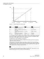
The diagram below illustrates the relationship between calibration digits and the calibration
weight.
Содержание SIWAREX WP231
Страница 16: ...Safety notes 2 1 General safety instructions SIWAREX WP231 16 Manual 07 2014 A5E31238908A 02 ...
Страница 24: ...Application planning 4 2 Parameter assignment options SIWAREX WP231 24 Manual 07 2014 A5E31238908A 02 ...
Страница 108: ...Scale parameters and functions 8 15 DR 15 tare settings SIWAREX WP231 108 Manual 07 2014 A5E31238908A 02 ...
Страница 131: ...Scale parameters and functions 8 26 DR 48 date and time 2 for Modbus SIWAREX WP231 Manual 07 2014 A5E31238908A 02 131 ...
Страница 132: ......
Страница 174: ...Technical data 13 3 Approvals SIWAREX WP231 174 Manual 07 2014 A5E31238908A 02 ...
Страница 180: ...List of abbreviations SIWAREX WP231 180 Manual 07 2014 A5E31238908A 02 ...
Страница 182: ...Index SIWAREX WP231 182 Manual 07 2014 A5E31238908A 02 ...

