Scale parameters and functions
8.8 DR 7 interface parameters
SIWAREX WP231
Manual, 07/2014, A5E31238908A-02
91
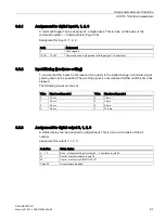
8.8.1
Assignment for digital input 0, 1, 2, 3
A command trigger can be assigned to a digital input. This is done on the basis of the
command number: →
Command lists (Page 139).
Assignment for input 0, 1, 2, 3:
Code
Assignment
0
Not assigned
10 001 ... 12 000
Command code is triggered at a falling edge (1->0 transition)
8.8.2
Input filtering (hardware setting)
To ensure that the inputs do not respond too quickly to the signal change, a minimum signal
pending time can be specified. The pending signal is not processed further until this time has
elapsed.
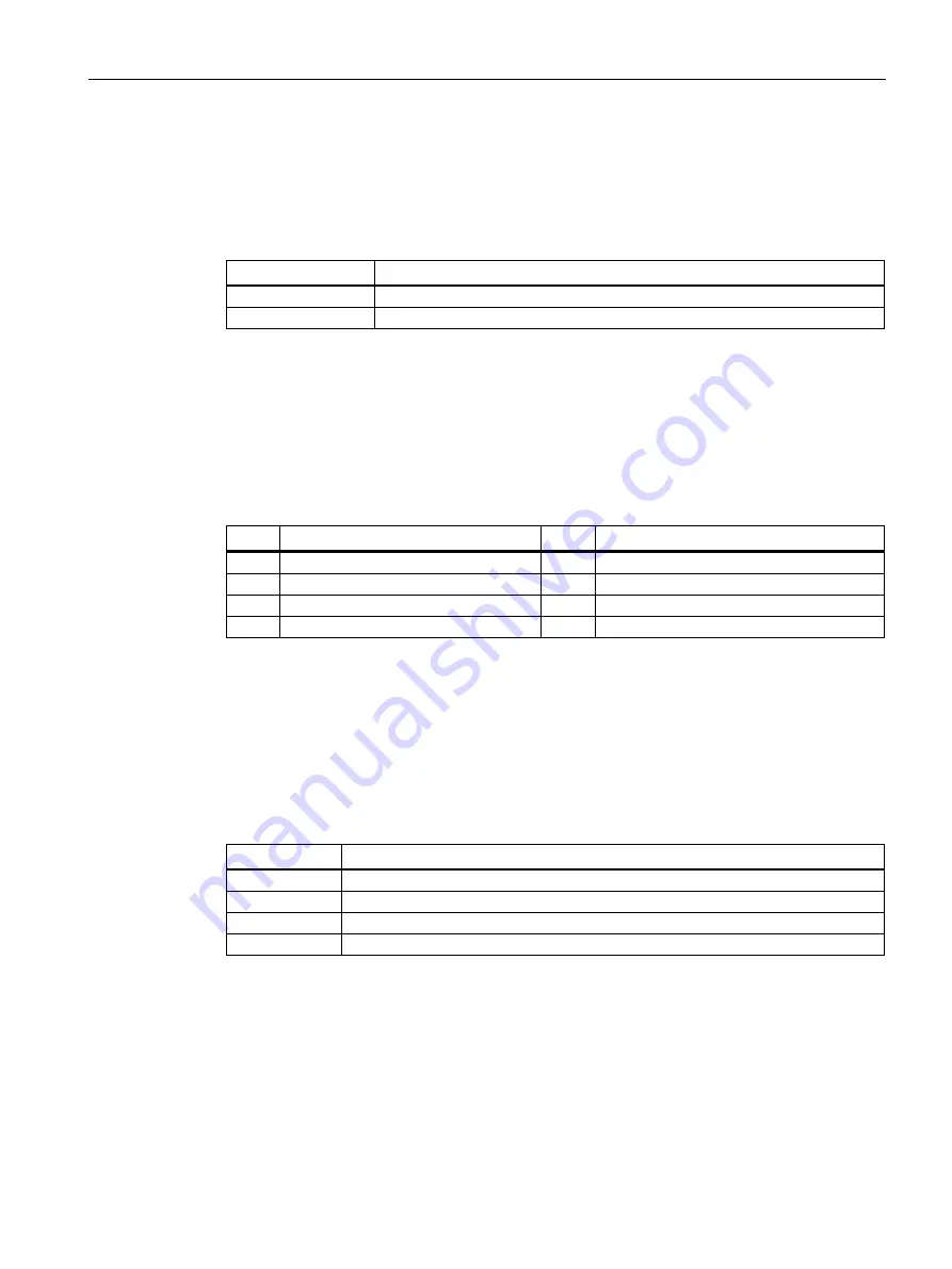
The following values can be set:
Value Signal pending period
Value
Signal pending period
0
0.2 ms
4
1.6 ms
1
0.2 ms
5
3.2 ms
2
0.4 ms
6
6.4 ms
3
0.8 ms
7
12.8 ms
8.8.3
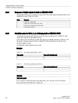
Assignment for digital output 0, 1, 2, 3
A status display can be assigned to a digital input. This is done on the basis of the bit
number.
Assignment for output 0, 1, 2, 3:
Code Hex
Status display
0 … 1F
Bit no. of the status flags from byte 0 .. 3 from data record 30
21
Control of output via data record 18
22
Control of output via SIMATIC S7 I/O
Code FF
Output always disabled
Содержание SIWAREX WP231
Страница 16: ...Safety notes 2 1 General safety instructions SIWAREX WP231 16 Manual 07 2014 A5E31238908A 02 ...
Страница 24: ...Application planning 4 2 Parameter assignment options SIWAREX WP231 24 Manual 07 2014 A5E31238908A 02 ...
Страница 108: ...Scale parameters and functions 8 15 DR 15 tare settings SIWAREX WP231 108 Manual 07 2014 A5E31238908A 02 ...
Страница 131: ...Scale parameters and functions 8 26 DR 48 date and time 2 for Modbus SIWAREX WP231 Manual 07 2014 A5E31238908A 02 131 ...
Страница 132: ......
Страница 174: ...Technical data 13 3 Approvals SIWAREX WP231 174 Manual 07 2014 A5E31238908A 02 ...
Страница 180: ...List of abbreviations SIWAREX WP231 180 Manual 07 2014 A5E31238908A 02 ...
Страница 182: ...Index SIWAREX WP231 182 Manual 07 2014 A5E31238908A 02 ...


