Configuration
6.2 Configuring the busbar run layout
SIVACON 8PS - Configuring with LX system
114
Configuration Manual, 10/2011, A5E02194899-02
6.2.2.3
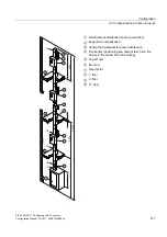
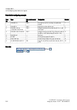
Planning in the case of vertical busbar runs
General procedure
The following applies when considering the layout of the busbar run:
●
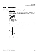
Recording of the determining busbar elements of the run: Feeder units, junction units and
end cap
●
Calculation of the run lengths between feeder units, junction units and end cap
●
Providinig feeder units with fixed points
●
Dividing run lengths into sub-lengths using fixed points.
●
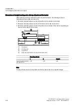
Configuring expansion compensation
●
Configuring fixing bracket per storey.
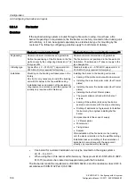
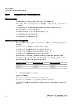
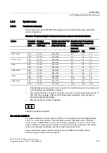
Maximum permissible sub-lengths L1
After recording the infeeds, junction units and end cap within a run, the following run layouts
can result:
●
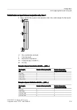
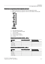
Busbar run layout between two junction units (Case 1)
●
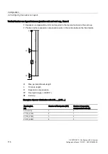
Busbar run layout between junction unit and end cap (Case 2)
●
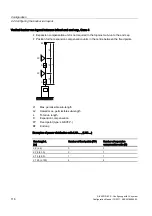
Busbar run layout between infeed and junction unit (Case 3)
●
Busbar run layout between infeed and end cap (Case 4).
Subdivision into the maximum permissible number of sub-lengths L1 then takes place.
Sub-length L1 depends on the conductor material of the busbar trunking system as well as
the purpose of use (power transmission or distribution):
Conductor material
Power transmission
Power distribution
1)
Cu (LXC....)
L1 ≤ 40 m
L1 ≤ 60 m
Al (LXA....)
L1 ≤ 25 m
L1 ≤ 50 m
1)
At least one tap-off unit per storey
These sub-lengths are
●
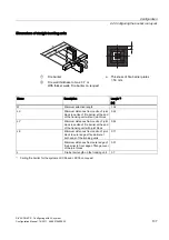
between two fixed points with expansion compensation
●
between fixed point and end cap without expansion compensation.
For sub-lengths between infeed and fixed point with expansion compensation, sub-length L1
is halved.
Содержание SIVACON 8PS
Страница 2: ......
Страница 206: ...Glossary SIVACON 8PS Configuring with LX system 204 Configuration Manual 10 2011 A5E02194899 02 ...
Страница 209: ......

