Detecting and Correcting Faults
6-5
SM 335 – High-Speed Analog Input/Output Module for the SIMATIC S7-300
6ES7 335-7HG00-8BA1
Measuring range 0 to 10 V
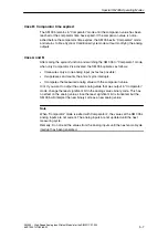
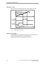
In the input range of 0 to 10 V, the open-wire test differs in that it is executed after
completion of A/D conversion of the active analog inputs. The test is executed by
outputting brief current pulses of approximately 30
m
A to the relevant input. The
SM 335 can detect an open wire by analyzing the resulting voltage difference.
In order to ensure that this form of open-wire test will function properly, the capac-
ity of the connecting cable and the sensors must not exceed 10 nF. In general,
cables of up to 30 m in length are no problem. The source resistance must not ex-
ceed 2.5 Kohms, as otherwise an open wire might be reported erroneously.
This is ensured when, e.g., a linear potentiometer with max. 10 Kohms is con-
nected.
(When the grinder is located at an intermediate point, the partial resistances must
be 5 Kohms and the cable connected in parallel, resulting in a resistance of
2.5 Kohms.)
Diagnostic interrupt enable
If the “Diagnostic interrupt” box is checked in HW Config and a diagnostic event
occurs, the module generates a diagnostic interrupt.
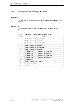
In addition, certain diagnostics can be switched on and off for specific channels
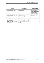
(see Table 6-1).
When the SM 335 generates a diagnostic interrupt, the CPU calls OB 82.
Note
It is possible to parameterize diagnostics monitoring in HW Config (e.g., open
wire) while disabling the diagnostic interrupt. If the diagnostics are modified, data
record 1 is also modified, and can always be read irrespective of parameter
assignment.

