Detecting and Correcting Faults
6-8
SM 335 – High-Speed Analog Input/Output Module for the SIMATIC S7-300
6ES7 335-7HG00-8BA1
6.5
Troubleshooting
Overview
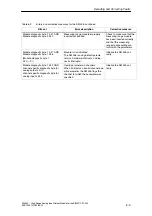
If you want to evaluate the diagnostic data in your program, Table 6-2 will help you
find the error description and corrective measure for the bits set in the diagnostic
data.
Table 6-2
Errors and corrective measures for the SM 335
Bits set
Error description
Corrective measure
Module diagnostic byte 1 bit 1 AND
Module diagnostic byte 3 bit 3
Internal hardware fault
Module is defective. Make a
note of the error description
d
t
t
SIEMENS
Module diagnostic byte 1 bit 1 AND
Module diagnostic byte 4 bit 2
Module outputs 0 V;
inputs are set to 7FFF
H
, counter value
is = FFFFFF
H
and contact your SIEMENS
representative.
Module diagnostic byte 1 bit 1 AND
Module diagnostic byte 4 bit 4
DA/AD conversion error
The relevant channel is set to 7FFF
H
or 0 V. Possible causes of error:
•
No 24 V load voltage or load volt-
age is less than 10 V
•
High-frequency interference dis-
turbing the measuring signal
•
A/D converter is defective
1. Check the load voltage.
2. Check the input signal
for high-frequency inter-
ference. You might have
an EMC problem.
3. Have the module chek-
ked and repaired if ne-
cessary.
Module diagnostic byte 1 bit 2 AND
Module diagnostic byte 1 bit 4
No 24 V load voltage or load voltage
less than 10 V; input values are set to
7FFF
H
.
Check load voltage.
Module diagnostic byte 1 bit 2 AND
Module diagnostic byte 1 bit 3 AND
channel-specific diagnostic byte for
analog input x bit 1
Common-mode error on input x
Check the connections at in-
put x.
Module diagnostic byte 1 bit 2 AND
Module diagnostic byte 1 bit 3 AND
channel-specific diagnostic byte for
analog input x bit 4
Open wire on input x
Module diagnostic byte 1 bit 2 AND
Module diagnostic byte 1 bit 3 AND
channel-specific diagnostic byte for
analog input x bit 6
Range violation (high) on input x
The error disappears when
the input voltage goes into
the nominal range or over-
range.
Module diagnostic byte 1 bit 2 AND
Module diagnostic byte 1 bit 3 AND
channel-specific diagnostic byte for
analog input x bit 7
Range violation (low) on input x
Module diagnostic byte 1 bit 2 AND
Module diagnostic byte 1 bit 3 AND
channel-specific diagnostic byte for
analog output x bit 2
Ground short on output x
Check the connections at
output x.

