Special SM 335 Operating Modes
5-12
SM 335 – High-Speed Analog Input/Output Module for the SIMATIC S7-300
6ES7 335-7HG00-8BA1
Note
To ensure compatibility with older module versions, the SM 335 has two
comparator modes.
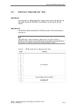
Comparator mode is set via bit 4:
Bit 4
=
0: mode 0 (Comparators 1 and 2 work on only one measuring channel; this
mode should only be set to ensure compatibility with older module versions)
Bit 4
=
1: mode 1 (Comparators 1 and 2 work on different or the same measuring
channels – see Figure 5-7, bit 3 to bit 0.
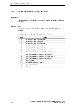
With comparator mode 0, the bit allocation (bit 3 to bit 0) shown in Figure 5-7 chan-
ges as follows:
•
0001 – Analog input CH0
•
0010 – Analog input CH1
•
0100 – Analog input CH2
•
1000 – Analog input CH3
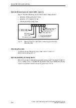
Comparator check byte (DS1, byte 12)
The Comparator check byte provides an additional means of checking the
comparator. The Comparator check byte has the following format:
7
6
5
4
3
2
1
0
Analog output CH0
Analog output CH1
Analog output CH2
Analog output CH3
Direction
Comparator 1
Comparator 2
Hardware interrupt
Fig. 5-8
Comparator check byte for “Comparator” mode
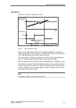
Direction (DS1, bit 12.7)
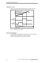
When bit 7 in the Comparator check byte is set to ’0’, the analog values are
compared in ascending order (as in Figure 5-8).
If bit 7 is set to ’1’, they are compared in descending order.


