Data Exchange with the SM 335
3-20
SM 335 – High-Speed Analog Input/Output Module for the SIMATIC S7-300
6ES7 335-7HG00-8BA1
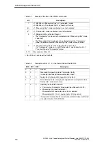
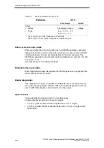
Analog input measuring range (DR1, Byte 2-5)
The default parameters for the analog input measuring range depend on the set-
ting on the SM 335’s measuring range module.
Table 3-12
Parameters for the analog input measuring range
Measuring range
module
setting
Default parameters
(byte address in relation to data
record 1)
Permissible parameters
and measuring ranges
(bytes 2 to 5)
A
Byte 2 (CH0): 19
H
(Voltage)
Byte 3 (CH1): 19
H
(Voltage)
Byte 4 (CH2): 19
H
(Voltage)
Byte 5 (CH3): 23
H
(Current)
For measuring voltage
14
1 V
1 V
B
This measuring range
module setting
is not allowed.
Byte 2 (CH0): 00
H
Byte 3 (CH1): 00
H
Byte 4 (CH2): 00
H
Byte 5 (CH3): 00
H
14
H
: – 1 V to + 1 V
15
H
: – 2.5 V to + 2.5 V
18
H
: 0 V to + 10 V
19
H
: – 10 V to + 10 V
1C : 0 V to + 2 V
C
Byte 2 (CH0): 19
H
(Voltage)
Byte 3 (CH1): 19
H
(Voltage)
Byte 4 (CH2): 23
H
(Current)
Byte 5 (CH3): 23
H
(Current)
1C
H
: 0 V to + 2 V
For measuring current
21
H
: – 10 to + 10 mA
22
H
: 0 mA to + 20 mA
D
Byte 2 (CH0): 19
H
(Voltage)
Byte 3 (CH1): 19
H
(Voltage)
Byte 4 (CH2): 19
H
(Voltage)
Byte 5 (CH3): 19
H
(Voltage)
22
H
: 0 mA to + 20 mA
23
H
: 4 mA to + 20 mA
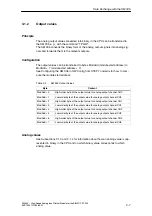
Output range for analog output (DR1, Bytes 6-9)
Permissible measuring ranges:
•
19
H
=
+/
–
10 V (default)
•
18
H
=
0
–
10 V
Channel assignment:
•
Byte 6
= Analog output channel CH0
•
Byte 7
= Analog output channel CH1
•
Byte 8
= Analog output channel CH2
•
Byte 9
= Analog output channel CH3

