Connecting the Inputs and Outputs of the SM 335
2-2
SM 335 – High-Speed Analog Input/Output Module for the SIMATIC S7-300
6ES7 335-7HG00-8BA1
2.1
Basic information about connecting the SM 335
Connecting the analog inputs and outputs
You can find detailed information about connecting the analog inputs and outputs in
the SIMATIC Programmable Logic Controller, S7-300 Module Data Reference Ma-
nual.
Rules
The following applies:
•
The cables must be twisted-pair cables, protected against interference and
shielded.
•
The accuracy of your measurements depends on the following:
– Load
– Cable between the SM 335 and the load
– Reference voltage
Power supply
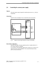
The SM 335 must be supplied with 24 V DC. The 24 V must be connected to
L+ (PIN 1), the 24 V’s zero potential to M (PIN 20).
Grounding
You can ground the 24 V power supply in the following way:
•
Direct on the 24 V power supply unit or
•
On the S7 CPU (if you use the 24 V power supply on the CPU).


