5-3
S7-200 Programmable Controller, CPU 210
C79000-G7076-C235-01
5.2
Contact Instructions
Standard Contacts
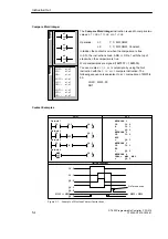
The Normally Open contact is closed (on) when the bit value of
address n = 1.
In STL, the normally open contact is represented by the Load,
And, and Or instructions. These instructions Load, AND, or OR
the bit value of address n to the top of the stack.
The Normally Closed contact is closed (on) when the bit value
of address n = 0.
In STL, the normally closed contact is represented by the Load
Not, And Not, and Or Not instructions. These instructions
Load, AND, or OR the logical Not of the bit value of address n to
the top of the stack.
Operands:
n:
I, M, SM
These instructions obtain the referenced value from the image
register, which is updated at the beginning of each CPU scan.
Not
The Not contact changes the state of power flow. When power
flow reaches the Not contact, it stops. When power flow does
not reach the Not contact, it sources power flow.
In STL, the Not instruction changes the value on the top of the
stack from 0 to 1, or from 1 to 0.
Operands:
none
Positive, Negative Transition
The Positive Transition contact allows power to flow for one
scan for each off-to-on transition. In STL, the Positive Transition
contact is represented by the Edge Up instruction. Upon
detection of a 0-to-1 transition in the value on the top of the
stack, the top of the stack value is set to 1; otherwise, it is set to
0.
The Negative Transition contact allows power to flow for one
scan, for each on-to-off transition. In STL, the Negative
Transition contact is represented by the Edge Down instruction.
Upon detection of a 1-to-0 transition in the value on the top of
the stack, the top of the stack value is set to 1; otherwise, it is
set to 0.
Operands:
none
You can have a total of 32 transition instructions in a program. These can be any
combination of Positive Transition (EU) and Negative Transition (ED) instructions.
Instruction Set
L
A
D
S
T
L
LD
n
A
n
O
n
LDN
n
AN
n
ON
n
n
n
/
L
A
D
S
T
L
NOT
NOT
L
A
D
S
T
L
P
N
EU
ED
Содержание Simatic S7-200 CPU 210
Страница 10: ...x S7 200 Programmable Controller CPU 210 C79000 G7076 C235 01 Contents ...
Страница 68: ...3 28 S7 200 Programmable Controller CPU 210 C79000 G7076 C235 01 Getting Started with a Sample Program ...
Страница 116: ...A 16 S7 200 Programmable Controller CPU 210 C79000 G7076 C235 01 CPU 210 Data Sheets ...
Страница 126: ...F 2 S7 200 Programmable Controller CPU 210 C79000 G7076 C235 01 CPU 210 Order Numbers ...
Страница 138: ...Index 12 S7 200 Programmable Controller CPU 210 C79000 G7076 C235 01 Index ...


