


2-17
S7-200 Programmable Controller, CPU 210
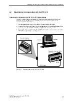
C79000-G7076-C235-01
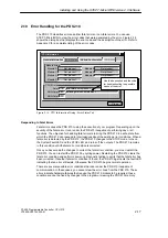
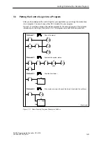
2.10 Error Handling for the PDS 210
The PDS 210 classifies errors as either fatal errors or non-fatal errors. You can use
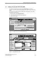
STEP 7-Micro/WIN to view the error codes that were generated by the error. Figure 2-16
shows the dialog box that displays the error code and the description of the error. Refer to
Appendix C for a complete listing of the error codes.
CPU Information
General Information
Close
Error Status
Module Configuration
Module Errors
Module 0:
Module 1:
Module 2:
Module 3:
Not present
Not present
Not present
Not present
Module 4:
Module 5:
Module 6:
Not present
Not present
Not present
CPU Errors
Fatal:
NON-Fatal:
0
83
No fatal errors present.
Missing main end statement.
Use the description and the code
for troubleshooting the possible
cause of the error.
DP Status
NON-Fatal:
11
Figure 2-16 CPU Information Dialog: Error Status Tab
Responding to Fatal Errors
Fatal errors cause the PDS 210 to stop the execution of your program. Depending upon the
severity of the fatal error, it can render the PDS 210 incapable of performing any or all
functions. The objective for handling fatal errors is to bring the PDS 210 to a safe state from
which the PDS 210 can respond to interrogations about the existing error conditions. When a
fatal error is detected by the PDS 210, the PDS 210 changes to the STOP mode, turns on
the System Fault LED and the STOP LED, and turns off the outputs. The PDS 210 remains
in this condition until the fatal error condition is corrected.
Once you have made the changes to correct the fatal error condition, you must restart the
PDS 210. You can restart the PDS 210 by cycling power. Restarting the PDS 210 clears the
fatal error condition and performs power-up diagnostic testing to verify that the fatal error has
been corrected. If another fatal error condition is found, the PDS 210 again sets the fault LED
indicating that an error still exists. Otherwise, the PDS 210 begins normal operation.
There are several possible error conditions that can render the PDS 210 incapable of
communication. In these cases, you cannot view the error code from the PDS 210. These
errors indicate hardware failures that require the PDS 210 module to be repaired; these
conditions cannot be fixed by changes to the program or clearing the PDS 210 memory.
Installing and Using the STEP 7-Micro/WIN Version 2.0 Software
Содержание Simatic S7-200 CPU 210
Страница 10: ...x S7 200 Programmable Controller CPU 210 C79000 G7076 C235 01 Contents ...
Страница 68: ...3 28 S7 200 Programmable Controller CPU 210 C79000 G7076 C235 01 Getting Started with a Sample Program ...
Страница 116: ...A 16 S7 200 Programmable Controller CPU 210 C79000 G7076 C235 01 CPU 210 Data Sheets ...
Страница 126: ...F 2 S7 200 Programmable Controller CPU 210 C79000 G7076 C235 01 CPU 210 Order Numbers ...
Страница 138: ...Index 12 S7 200 Programmable Controller CPU 210 C79000 G7076 C235 01 Index ...