Index-7
S7-200 Programmable Controller, CPU 210
C79000-G7076-C235-01
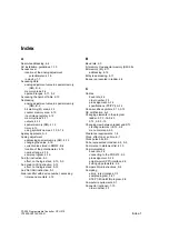
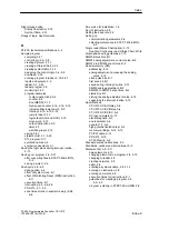
Mounting
agency certifications and specifications, A-3
clearance requirements, 1-4
dimensions
CPU 210, 1-5
DIN rail, 1-5
PDS 210, 1-5
in a panel box, 1-7
on a DIN rail, 1-6
on a panel, 1-6
screw size, 1-6
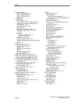
Move instruction, Move Word (MOVW), 5-10
Move Word (MOVW) instruction, 5-10
Move Word (MOVW) instructions, example,
5-10–5-12
N
Negative Transition (ED) instruction, 5-3
Networks
in ladder, 2-7
in STL, 2-8
keyword “network”, 2-8
represented in ladder, 4-9
Non-fatal errors, responding to, 2-18
Normally Closed Contact instruction, 5-3
Normally Open Contact instruction, 5-3
NOT instruction, 5-3
Number of characters per symbol, 2-13
Number of symbols allowed, 2-13
Numbers, representation of, 4-11
O
OB1.
See Program
On-Delay Timer instruction, 5-6
Online help, STEP 7-Micro/WIN, 2-1
Operand, 4-10
Or (O) / Or Not (ON), effect on the logic stack, 5-3
Or (O) instruction, 5-3
effect on the logic stack, 4-10
Or Load (OLD) instruction, 5-13
effect on the logic stack, 5-13
Or Not (ON) instruction, 5-3
Order numbers, F-1
Output (coil) instruction, 5-5
represented in ladder, 4-9
Output instructions, 5-5
coil, 5-5
example, 5-5
represented in ladder, 4-9
Reset (R), 5-5
Set (S), 5-5
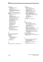
Outputs
addressing, 4-12
basic operation, 4-4
represented in ladder, 4-9
writing to, 4-6–4-9
Overview
CPU 210, 1-1–1-4
PDS 210, 1-1–1-4
P
Panel box
See also Enclosure
installing in a, 1-7
Paste, copy, and cut
in a Status Chart, 2-15
in a Symbol Table, 2-14
PC/PPI cable
baud rate, 2-3
order number, F-1
pin assignments, A-14
specifications, A-14
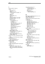
PDS 210
agency approvals, A-2
analog adjustment
location of the potentiometer, 4-16
value stored in special memory (SM), B-2
basic operation, 4-4
baud rate, 2-3
compile rule violations, C-1
debug option, scan cycle, 4-8
dimensions, 1-5
downloading a program, 2-10–2-12
electromagnetic specifications, A-3
environmental specifications, A-2
equipment requirements, 1-2
execution times, E-1
fatal errors, C-1
general technical specifications, A-2
high potential isolation test, A-3
input simulator, order number, F-1
interrupt routine, guidelines and restrictions,
5-15
logic stack, 4-10
memory areas, 4-11–4-13
memory cartridge location, A-11
order numbers, F-1
organizing the program, 4-5
product overview, 1-1–1-4
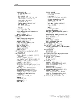
scan cycle, 4-6–4-9
debug option, 4-8
effect of Watchdog Reset (WDR)
instruction, 5-11
Index
Содержание Simatic S7-200 CPU 210
Страница 10: ...x S7 200 Programmable Controller CPU 210 C79000 G7076 C235 01 Contents ...
Страница 68: ...3 28 S7 200 Programmable Controller CPU 210 C79000 G7076 C235 01 Getting Started with a Sample Program ...
Страница 116: ...A 16 S7 200 Programmable Controller CPU 210 C79000 G7076 C235 01 CPU 210 Data Sheets ...
Страница 126: ...F 2 S7 200 Programmable Controller CPU 210 C79000 G7076 C235 01 CPU 210 Order Numbers ...
Страница 138: ...Index 12 S7 200 Programmable Controller CPU 210 C79000 G7076 C235 01 Index ...


