Index-9
S7-200 Programmable Controller, CPU 210
C79000-G7076-C235-01
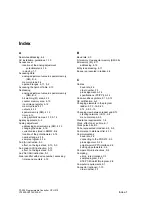
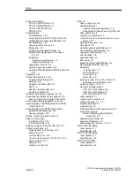
Right mouse button
Status Chart editor, 2-15
Symbol Table, 2-14
Rungs of logic.
See Networks
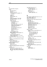
S
S7-200, technical specifications, A-2
Sample program
compiling, 3-21
control logic, 3-4–3-8
creating a project, 3-13
creating a Status Chart, 3-22
creating symbol table, 3-14
designing the control logic, 3-4–3-8
download, 3-23
entering program in ladder, 3-15–3-21
inputs and outputs, 3-2
ladder, 3-1–3-25
ladder program, 3-9
monitoring, 3-23
program examples
contact instructions, 5-4
counter, 5-8
End (MEND), 5-12
high-speed counter, 4-14–4-16, 5-16
increment/decrement word, 5-9
interrupt, 4-14–4-16, 5-16
jump to label, 5-12
logic stack (ALD and OLD), 5-13
move word, 5-10
output instructions, 5-5
timer, 5-7
watchdog reset, 5-12
saving, 3-21
statement list, 3-1–3-25
STL program, 3-11
symbolic names, 3-2
system requirements, 3-1
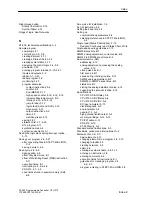
Saving the logic stack during interrupt routine,
5-15
Saving your program, 2-6, 3-21
after converting files to STEP 7-Micro/WIN,
D-2
saving a project, 2-6
Scan cycle, 4-6–4-9
debug option, 4-8
effect of system clock, E-1
effect of Watchdog Reset (WDR) instruction,
5-11
execution times, E-1
interrupting, 4-5, 4-6–4-9
PDS 210, 4-7–4-9
scan times stored in special memory (SM),
B-2
Screw size for installation, 1-6
Set (S) instruction, 5-5
Setting the baud rate, 2-3
Setting up
communication parameters, 2-4
selecting preferences in STEP 7-Micro/WIN,
2-5
Single read (Status Chart option), 2-15
See also Continuous read; Status Chart; Write
Single-phase wiring guidelines, 1-10
SMW0 status bits, B-1
SMW2 analog adjustment, current value, B-2
SMW22 to SMW26 scan times, B-2
Special memory (SM)
addressing, 4-12
analog adjustment, accessing the analog
value, 4-12
clock pulse bits, B-1
first scan bit, B-1
saved during interrupt routine, 5-15
SMW2 analog adjustment, B-2
SMW22 to SMW26 scan times, B-2
status bits, B-1
storing the analog adjustment value, 4-16
supporting the interrupt routine, 5-15
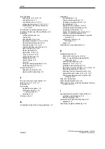
Specifications
CPU 210 AC/AC/Relay, A-8
CPU 210 AC/DC/Relay, A-6
CPU 210 DC/DC/DC, A-4
DC input simulator, A-15
electromagnetic, A-3
environmental, A-2
general, 1-3, A-2
high potential isolation test, A-3
memory cartridge, A-12, A-13
PC/PPI cable, A-14
PDS 210, A-10
S7-200 family, A-2
Standard contact instructions, 5-3
Standards, national and international, A-2
Statement list, 4-9–4-11
basic elements, 4-10
changing elements in a program, 2-8, 3-15
changing to ladder, 2-9
creating networks, 2-8
editor, 2-8
entering a symbolic name, 2-8, 3-14
entering an instruction, 2-8
entering comments, 2-8
execution times for instructions, E-1
guidelines for creating a program, 2-8,
4-2–4-3
program, entering in STEP 7-Micro/WIN, 2-8
Index
Содержание Simatic S7-200 CPU 210
Страница 10: ...x S7 200 Programmable Controller CPU 210 C79000 G7076 C235 01 Contents ...
Страница 68: ...3 28 S7 200 Programmable Controller CPU 210 C79000 G7076 C235 01 Getting Started with a Sample Program ...
Страница 116: ...A 16 S7 200 Programmable Controller CPU 210 C79000 G7076 C235 01 CPU 210 Data Sheets ...
Страница 126: ...F 2 S7 200 Programmable Controller CPU 210 C79000 G7076 C235 01 CPU 210 Order Numbers ...
Страница 138: ...Index 12 S7 200 Programmable Controller CPU 210 C79000 G7076 C235 01 Index ...

