4-3
S7-200 Programmable Controller, CPU 210
C79000-G7076-C235-01
Designing the Safety Circuits
Identify equipment requiring hard-wired logic for safety. Control devices can fail in an unsafe
manner, producing unexpected startup or change in the operation of machinery. Where
unexpected or incorrect operation of the machinery could result in physical injury to people
or significant property damage, consideration should be given to to the use of
electro-mechanical overrides which operate independently of the CPU 210 to prevent unsafe
operations.
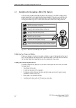
The following tasks should be included in the design of safety circuits:
S
Identify improper or unexpected operation of actuators that could be hazardous.
S
Identify the conditions that would assure the operation is not hazardous, and determine
how to detect these conditions independently of the CPU 210.
S
Identify how the CPU 210 and its I/O will affect the process when power is applied and
removed, and on detected errors. This information should only be used for designing for
the normal and expected off-normal operation, and should not be relied on for safety
purposes.
S
Design manual or electro-mechanical safety overrides that will block the hazardous
operation independent of the CPU.
S
Provide appropriate status information from the independent circuits to the CPU 210 so
that the program and any operator interfaces have necessary information.
S
Identify any other safety-related requirements for safe operation of the process.
Specifying the Operator Stations
Based on the requirements of the functional specifications, create drawings of the operator
station. Include the following items:
S
Overview showing the location of each operator station in relation to the process or
machine
S
Mechanical layout of the devices (display, switches, lights, etc.) for the operator station
S
Electrical drawings with the associated I/O of the CPU 210
Creating the PLC Configuration Drawings
Based on the requirements of the functional specification, create configuration drawings of
the control equipment. Include the following items:
S
Overview showing the location of the CPU in relation to the process or machine
S
Mechanical layout of the CPU 210 (including cabinets and other equipment)
S
Electrical drawings for each CPU 210 (including the device model numbers and I/O
addresses)
Creating a List of Symbolic Names
If you choose to use symbolic names for addressing, create a list of symbolic names for the
absolute addresses. Include not only the physical I/O signals, but also the other elements
that will be used in your program.
Basic Concepts for Programming the CPU 210
Содержание Simatic S7-200 CPU 210
Страница 10: ...x S7 200 Programmable Controller CPU 210 C79000 G7076 C235 01 Contents ...
Страница 68: ...3 28 S7 200 Programmable Controller CPU 210 C79000 G7076 C235 01 Getting Started with a Sample Program ...
Страница 116: ...A 16 S7 200 Programmable Controller CPU 210 C79000 G7076 C235 01 CPU 210 Data Sheets ...
Страница 126: ...F 2 S7 200 Programmable Controller CPU 210 C79000 G7076 C235 01 CPU 210 Order Numbers ...
Страница 138: ...Index 12 S7 200 Programmable Controller CPU 210 C79000 G7076 C235 01 Index ...


